
Technical information


COPYRIGHT
©
2001 CANON INC.
2000 2000 2000 2000
CANON CLC5000 REV.0 JAN. 2001
CHAPTER 3 INSTALLATION
3-28
Step Work Remarks
F03-400-04
F03-400-05
F03-400-06
Screw
Screw
Fixing assembly
Screw
Screw
Fixing assembly (rear)
Fixing assembly
mount (front)
Oil receptacle
Screw
Oil tank
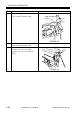
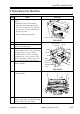
8 Remove the two screws, and remove the
fixing assembly.
Be sure to fit the two screws
removed in step 6 in advance
of this step.
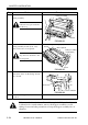
9 Remove the two screws, and remove the
fixing assembly mount (front, rear);
then, remove the oil receptacle.
At this time, take care not to
drop the hose attached to the
oil receptacle.
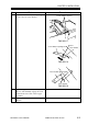
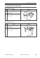
10 Remove the screw, and remove the oil
tank; then, draw out the fixing oil from
the oil tank.
11 Return the fixing unit to its initial
position.
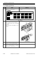
If the route of relocation is not flat and the copier is likely to be subjected
to vibration for several minutes, remove the hopper assembly to avoid
caking of toner and take precautions to keep the hopper assembly free of
vibration.