
Technical information


COPYRIGHT
©
2001 CANON INC. 2000 2000 2000 2000 CANON CLC5000 REV.0 JAN. 2001
CHAPTER 5 TROUBLESHOOTING IMAGE FAULTS/MALFUNCTIONS
5-57
e.Initializing the RAM on the Reader Controller PCB
1) Record the settings of user mode.
2) Execute ‘FUNC>R-CON>RAM-CLR’ in service mode. (The power switch will auto-
matically turn off.)
3) Turn on the power switch.
4) Execute ‘FUNC>CCD>AUTO-ADJ’ in service mode. (about 8 min)
5) If a projector is installed, execute ‘FUNC>PROJ-ADJ>PROJ-CCD’ in service mode.
6) Enter any new user mode settings and the settings recorded in B of the service label.
(If you have changed any other service mode settings related to the reader controller,
enter such settings.)
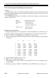
Service Mode Settings Related to the Reader Controller
ADJUST Settings on ADJ-XY screen
Settings on DOC-REC screen
Settings on PROJ screen
Settings on ED/RF screen
Settings on COL-ADJ screen
Settings on ADJ-MIS screen
Settings on PRJ-ADJ screen
OPTION Settings on R-OPT screen
Settings on ON-SET on R-OPT screen
Settings on REMOTE screen
Settings on DECK screen
The above service mode settings are cleared when the RAM on the reader controller is
initialized.
f. When Replacing the Image Position Correction CCD Unit
1) After replacing the image position correction CCD unit, execute ‘FUNC>INSTALL
(2nd screen)>REG-APER’ in service mode.
Thereafter, be sure to turn off and on the power switch to correct the image position.
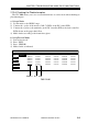
g. When Replacing the Paper Thickness Sensor
1) Check the settings (A through E) recorded on the label attached to the paper thickness
sensor you are replacing, and record them under ‘SNSR-RNK’ on the service label. At
this time, you need not perform step 3) and the subsequent steps if the settings are the
same as the settings under ‘FUNC>P-THICK>SNSR-RNK’ of service mode.
2) Replace the power thickness sensor.
3) Enter the settings you recorded on the service label in step 1) under ‘FUNC>P-
THICK>SNSR-RNK’ in service mode. (Each press on ‘SNSR-RNK’ toggles the set-
tings A through E.)
4) Check to make sure that the values of ‘P-TH-1’ and ‘P-TH-2’ are identical to the val-
ues recorded on the service label; if different, enter the correct values using ‘FUNC-
DC-CON (5/5)>P-TH-1/2’ in service mode.
5) End service mode.