
Technical information

COPYRIGHT
©
2001 CANON INC.
2000 2000 2000 2000
CANON CLC5000 REV.0 JAN. 2001
CHAPTER 5 TROUBLESHOOTING IMAGE FAULTS/MALFUNCTIONS
5-135
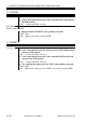
4.1.24 E076
1) Execute ‘FUNC>F-MISCP>MTR>13’ in service mode to rotate the
transfer cleaner web motor (M12). Does the motor rotate?
YES: Go to step 3.
Overload
2) Turn the transfer cleaner web by hand. Is the rotation heavy?
NO: Check the transfer cleaner web drive system.
Transfer cleaner web motor (M12)
DC controller PCB
3) Set the meter to the 5VDC range, and measure the voltage between
J2218-A1 (+: M12ON) and J2218-A4 (-: GND). Does it change from
about 5 V to about 0 V when the motor is rotated in service mode?
YES: Replace the transfer cleaner web motor (M12).
NO: Check the wiring from J2218A to the transfer cleaner web motor
(M12); if normal, replace the DC controller PCB.
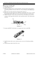
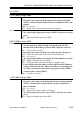
4.1.25 E077
1) Make copies. Does the transfer belt waste toner motor (M31) ro-
tate?
YES: Go to step 3.
Overload
2) Turn the transfer cleaner waste toner feeding screw by hand. Is the
rotation heavy?
NO: Check the transfer cleaner waste toner feeding screw drive system.
Transfer belt waste toner motor (M31)
DC controller PCB
3) Set the meter to the 24VDC range, and measure the voltage be-
tween J218-B12 (+: M3ON) and J2218-B3 (-: GND). Make copies;
does it change from about 24 V to about 0 V when the motor ro-
tates?
YES: Replace the transfer belt waste toner motor (M31).
NO: Check the wiring from J2218B to the transfer belt waste toner mo-
tor (M31); if normal, replace the DC controller PCB.