
Technical information


2-24
CHAPTER 2 NEW FUNCTIONS
COPYRIGHT
©
2001 CANON INC. 2000 2000 2000 2000 CANON CLC5000 REV.0 JAN. 2001
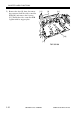
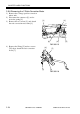
When removing the laser scan-
ner motor, be sure to work
while paying attention to the
lenses found to the left and the
right of the motor assembly and
the dust-proofing glass of the
motor assembly.
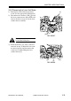
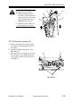
When mounting the laser scan-
ner motor, do not force the har-
ness while connecting the con-
nector to the laser scanner mo-
tor driver PCB to avoid discon-
necting the connector.
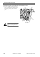
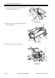
When mounting the laser scan-
ner drive PCB, take care not to
slant or peel the sticker [6]
found on the back of the sup-
port plate.
[6]
F02-305-09