Video Product DC10 E, DC20 E No. D17-9213, 9313 c CANON INC. 2005 Digital Video Camera iPAL Canon Inc. Digital Imaging Products Service & Quality Assurance Dept. First Edition : Sep. 2005 First Print : Sep.
GENERAL DESCRIPTION OF PRODUCT CONTENTS 1.
DC10 E, DC20 E GENERAL DESCRIPTION OF PRODUCT 1.
DC10 E, DC20 E GENERAL DESCRIPTION OF PRODUCT 1-2 List of Main Features 1-2-1 High Image Quality (1) Total pixels/CCD size DC10 E : approx. 1.33-megapixel, 1/4-inch CCD (color correction filter) featured DC20 E : approx. 2.20-megapixel, 1/3.9-inch CCD (primary color filter) featured (2) Effective pixels DC10 E Still image (CARD/DISC) : Video (DISC only) Approx. 1.23-megapixel (1280 [H] × 960 [V]) : 4:3 Widescreen TV (IS OFF) → Approx. 860,000 pixels (1072 [H] × 804 [V]) → Approx.
DC10 E, DC20 E GENERAL DESCRIPTION OF PRODUCT (4) Many program AE options (same as MVX1 Si E, MVX1 S E but a 3-position slide switch is featured) 1) AUTO, 2) P (P, Tv, Av mode), 3) SCN SCN (special scene) mode can be selected to enable optimum shooting of the eight types of scenes below. <1> Portrait : This is used to defocus the background to set off the subject to be shot. <2> Sports <3> Night : This is used to shoot fast-moving subjects during tennis matches and games of golf, for instance.
DC10 E, DC20 E GENERAL DESCRIPTION OF PRODUCT (10) Auto slow shutter function (set by the MENU button) The slow-side shutter speeds for Auto mode were expanded. During movie : 1/50 sec → 1/25 sec During still image : 1/25 sec → 1/12.5 sec This enables shooting of subjects in low brightness.
DC10 E, DC20 E GENERAL DESCRIPTION OF PRODUCT Comfortable Operation/Miscellaneous (1) New omni selector adopted (2) Finalize button included (3) Lens cover incorporated inside the body (same as MVX1 Si E, MVX1 S E) (4) PRINT/SHARE button included (1) (2) (4) When connected to a Direct printer, pressing the button when it is lit blue will print the still image displayed on the LCD monitor. When connected to a computer, files selected on the LCD monitor can be transferred.
DC10 E, DC20 E GENERAL DESCRIPTION OF PRODUCT (17) Execute/release finalizing (finalizing can be released only for DVD-RW discs) (18) Accessories (same as MVX1 Si E, MVX1 S E) Tele-Converter TL-H27, Wide Converter WD-H27, Filter Set FS-H27U Battery Pack BP-208 (850 mAh), Battery Charger CG-300 (E), Multi Cable MTC-100 (19) “MY DVD software” (Roxio MyDVD for Canon) This software makes it easy to burn original DVDs on home-use personal computers.
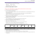
DC10 E, DC20 E GENERAL DESCRIPTION OF PRODUCT 1-3 Product Specifications Comparison Chart Specifications Lens DC10 E DC20 E Movie Lens10× optical zoom Still image Lens10× optical zoom CCD Image stabilizer 1/4-inch, 1/3.9-inch, 1.33-megapixel color correction filter 2.2-megapixel RGB primary color filter Electronic system Electronic system (number of effective pixels 850,000 pixels) (number of effective pixels 1.77-megapixel) Monitor 2.5-inch, 123,000-pixel LCD monitor EVF 0.
DC10 E, DC20 E GENERAL DESCRIPTION OF PRODUCT 1-4 Function and Performance List Item DC10 E DC20 E 1/4-inch CCD 1/3.9-inch CCD Interlacing Interlacing (Color correction filter) (RGB primary color filter) 1.33-megapixel 2.20-megapixel Approx. 850,000 pixels (4:3) Approx. 1.77-megapixel (4:3) Approx. 1.23-megapixel Approx. 2.00-megapixel Camera Image sensor Image size System (filter) Total pixels Number of effective pixels Movie Still image Lens Nominal focal length 4.05 to 40.
DC10 E, DC20 E GENERAL DESCRIPTION OF PRODUCT Item DC10 E DC20 E Shooting functions Shutter speed Shutter speed setting Movie 9 levels (1/6, 1/12.5, 1/25, 1/50, 1/120, 1/250, 1/500, 1/1000, 1/2000) (in Tv mode) Still image 9 levels (1/2, 1/3, 1/6, 1/12.5, 1/25, 1/50, 1/120, 1/250, 1/500) Auto mode Movie 1/25 to 1/500 sec (with auto slow shutter ON), 1/50 to 1/500 sec (with auto slow shutter OFF) Still image 1/12.
DC10 E, DC20 E GENERAL DESCRIPTION OF PRODUCT Item DC10 E DC20 E Shooting functions Still image recording Compression method JPEG Single image ● Continuous shooting (card recording only) ● AEB (card recording only) ● Exposure correction amount (steps of ±0, -0.5, +0.
DC10 E, DC20 E GENERAL DESCRIPTION OF PRODUCT Item DC10 E DC20 E PLAY mode Playback effects ● (Not possible during still image playback and movie playback) Playback zoom (5× zoom) D. effects Movie × Still image × D.
DC10 E, DC20 E GENERAL DESCRIPTION OF PRODUCT ● External View Note : Figure shows DC 20 E. External differences from DC10 E : Only the flash and the mini video light in the front. Fig.
DC10 E, DC20 E GENERAL DESCRIPTION OF PRODUCT 2. Technical Explanation 2-1 Design Concept The photograph shows DC20 E. * Circle grip styling for superior operability. Circle grip with a key positioned at the arc of the disc area. Fits snugly in the user’s hand to assure superior operability. * Distinctive and attractive rounded rear shape. Design where the cylindrical shape of the lens continues from the front right through to the rear panel along the arc of the disc area.
DC10 E, DC20 E GENERAL DESCRIPTION OF PRODUCT Differences in external appearance between DC10 E and DC20 E 1. Paint color used for rear cover 2. Grip cover (DC20 E : painted; DC10 E : not painted) Differences in appearance by market The coloring of DC10 E and DC20 E is the reverse of the Japanese specification in overseas markets.
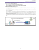
DC10 E, DC20 E GENERAL DESCRIPTION OF PRODUCT 2-2 TS Mech The TS Mech is the DVD drive newly developed for DVD cameras. It consists of a mechanical section and a control board. TS Mech Size Depth 70 mm Width 84 mm Height 14.3 mm Weight 100 g 2× Playback/recording speed Usable disc DVD-R, DVD-RW (1.4 GB, 8 cm) 2-2-1 Overview of TS Mech TS Mech 14.3mm 84mm 70mm Fig.
DC10 E, DC20 E GENERAL DESCRIPTION OF PRODUCT 2-2-2 Main Mechanical Parts Spindle motor Pick-up Control board Tracking motor Closeup of Pick-up Suspension Coil wiring material Material of lens protection Magnet Cover Magnet Coil wiring material Coil wiring material Suspension Fig.
DC10 E, DC20 E GENERAL DESCRIPTION OF PRODUCT 3. Performance DC10 E, DC20 E DVD video camera 1 Type 2 DVD recording modes 2-1 Movie Either DVD-Video Recording (VR mode) or DVD-VIDEO (VIDEO mode). DVD-R discs support DVD-VIDEO only. Movie compression method: MPEG2, Audio compression method: Dolby Digital 2ch (AC-32ch) [ 2-2 Still Image ]/sampling frequency 48 KHz Complies with Exif Ver 2.
DC10 E, DC20 E GENERAL DESCRIPTION OF PRODUCT 5 Camera 5-1 Image sensing device DC10 E : 1/4-inch interlaced CCD DC20 E : 1/3.9-inch interlaced CCD DC10 E : Approx. 1.33-megapixel DC20 E : Approx. 2.
DC10 E, DC20 E GENERAL DESCRIPTION OF PRODUCT 5-3 Digital zoom Still image Movie None DC10 E : - 40× / 200× DC20 E : - 40× / 200× 35 mm equivalent (at 4:3) DC10 E : Approx. 1868 mm/9340 mm DC20 E : Approx.
DC10 E, DC20 E GENERAL DESCRIPTION OF PRODUCT 5-6-4 Electronic shutter 5-6-4-1 In Auto mode Movie 5-6-4-2 5-6-4-3 5-6-4-4 5-6-4-5 5-6-4-6 1/30 to 1/500 sec (with auto slow shutter OFF) 1/25 to 1/500 sec (with auto slow shutter ON) Still image 1/25 to 1/500 sec (with auto slow shutter OFF) 1/12.5 to 1/500 sec (with auto slow shutter ON) When the image stabilizer is ON 1/100 When the image stabilizer is OFF 1/50 Slow Shutter mode None Av mode (Both Movie and Still image) Aperture setting F1.8, 2.0, 2.4, 2.
DC10 E, DC20 E GENERAL DESCRIPTION OF PRODUCT 2.5-inch color LCD Approx. 123,000 pixels (560 [H] × 220 [V]) TFT active-matrix drive. RGB delta arrangement; ON when LCD monitor not closed (when panel faces inwards) Angle adjustment Possible. Monitoring is possible for high-angle, low-angle, and mirror shooting. Information display Color display of operating mode, simple zoom position, remaining battery charge, remaining disc space, time code, warnings and other indications.
DC10 E, DC20 E GENERAL DESCRIPTION OF PRODUCT 5-12 Built-in microphone 5-12-1 Wind screen function 5-13 Built-in Flash Shooting (DC20 E only) 5-13-1 Flash modes 5-13-2 Shutter speed 5-13-3 Shooting distance 5-14 Auxiliary light source (DC20 E only) 5-14-1 Flash mode 5-15 Other additional functions 5-15-1 Disc counter 5-15-2 Data code a. Time and date Stereo (using electret condenser microphone) Omni-directional microphone × 2 + Electric circuitry for stereo Included. With ON/OFF switch (Menu selection.
DC10 E, DC20 E GENERAL DESCRIPTION OF PRODUCT 6 DVD Recorder section 6-1 Recording functions Camera shooting and recording only (analog line input recording is not possible), movie and audio is recorded to 8 cm DVD-R/-RW disc. When set to Disc Movie mode, movies are recorded in a 8 cm DVD-R/-RW disc in VR mode or VIDEO mode. However, recording is only possible in VIDEO mode for 8 cm DVD-R discs (automatic setting). The image quality setting mode can be selected from XP, SP, or LP (FUNC. menu selection).
DC10 E, DC20 E GENERAL DESCRIPTION OF PRODUCT 6-3 Editing functions 6-3-1 Original movie editing 6-3-2 Playlist editing 6-3-3 Disc title 6-3-4 Disc protect 6-3-5 Create photo movie 6-4 Finalize DVD-R This function edits movies or dics This function edits original movies (scenes) recorded in VR mode. Deleting, dividing and adding to playlist is possible. When images are recorded in the DVD-VIDEO mode (-RW disc) only the scene which has just been shot can be deleted.
DC10 E, DC20 E GENERAL DESCRIPTION OF PRODUCT 6-6 Output signals 6-6-1 DV terminal 6-6-2 Multi-pin a. Video signals Signal configuration Output Impedance Output Signal level Horizontal resolution Self recording/playback Camera EE OUT b. Audio signal Types of signals Output Impedance Output Signal level Frequency characteristics Audio signal S/N c.
DC10 E, DC20 E GENERAL DESCRIPTION OF PRODUCT 6-7-3 File names/folder names Based on the DCF (Design rule for Camera File systems) and still image (Exif 2.2) file management specifications / DPOF (Digital Print Order Format) file management specifications, the following names are assigned to recorded cards after initializing in the Initialization menu. CANON DV a. Card volume label Types of files Type Folder name and file name Still image (Exif 2.2) file JPEG //DCIM/xxxCANON/IMG_yyyy.
DC10 E, DC20 E GENERAL DESCRIPTION OF PRODUCT 6-7-7 Usable memory card miniSD memory card SanDisk : 16MB, 32 MB, 64 MB, 128 MB, 256 MB Matsushita Electric : 16MB, 32 MB, 64 MB, 128 MB, 256 MB Toshiba : 16MB, 32 MB, 64 MB, 128 MB, 256 MB 6-7-8 Number of continuous shots and number of stored continuous shots (card still image only) DC20 E Number of continuous shots recorded per second Image size Normal continuous High-speed continuous shooting shooting Flash recording Maximum continuousness number of r
DC10 E, DC20 E GENERAL DESCRIPTION OF PRODUCT 6-9-6 Print systems Print manufacturer Printer specifications Suitable printer Printer specifications when connected to DC10 E/ DC20 E Other manufacturer Canon CP specifications CP-10/100 Not supported CP specifications +PictBridge specifications CP-200/3002nd/220/ 330/400/500/600 BJ Photo specifications only CP specifications +PictBridge specifications BJ-895PD/535PD/F890PD, PIXUS 50i/80i/450i/470PD PIXUS 990i/900PD/ DS700 Not supported PictBridge
DC10 E, DC20 E GENERAL DESCRIPTION OF PRODUCT 6-10 Other functions 6-10-1 Automatic stop function 6-10-2 Power automatic stop function 6-10-3 Copy between media 6-10-4 World clock display 6-10-5 Speaker 6-10-6 Battery charging function Charging time 6-10-7 File transfer USB file transfer When forward still image playback is continued for approx. 5 minutes, or reverse still image playback is continued for approx. 5 minutes. When the disc end or beginning is reached.
DC10 E, DC20 E GENERAL DESCRIPTION OF PRODUCT 8 Power supply 8-1 Input power supply 8-2 Power consumption DC10 E DC20 E 7.4 V DC (battery pack), 8.4 V DC (DC IN) Shooting Playing Shooting Playing 9 Dimensions (W × H × D) 10 Weight 10-1 Main unit 10-2 Total equipped weight XP : Approx. 5.1 W, SP : Approx. 4.6 W, LP : Approx. 4.2 W (CVF) XP : Approx. 5.2 W, SP : Approx. 4.7 W, LP : Approx. 4.3 W (LCD Normal) XP : Approx. 5.3 W, SP : Approx. 4.8 W, LP : Approx. 4.4 W (LCD Bright) XP : Approx. 4.
DC10 E, DC20 E GENERAL DESCRIPTION OF PRODUCT 12 Relationship between DC10 E, DC20 E functions and modes *:Initial setting –: Cannot be set Settings can be changed, but operations are disabled. Backup is performed. Enabled when card simultaneous recording is ON. Settings can be made when card simultaneous recording is OFF, but operation is disabled. Backup is performed. Conditional backup is performed. Settings can be made when AF and Focus Priority is ON. Backup is performed.
DC10 E, DC20 E GENERAL DESCRIPTION OF PRODUCT Card Still Image P SCN AUTO Portrait Sports Night Snow Beach Sunset Spotlight Fireworks P Tv Av Large Recording pixels Medium Small Super Fine Compression ratio Fine Normal Simultaneous recording 640 x 480 OFF – – – – – – – – – – – – Fine – – – – – – – – – – – – Normal – – – – – – – – – – – – – – – – – – – – Auto Always On Flash (DC20 E only) OFF Red-eye Reduction Single shooting Drive mode Night
DC10 E, DC20 E GENERAL DESCRIPTION OF PRODUCT Disc Movie – – – – – – – – – – – – – – – – – – – – – – – – – – – – – – – – – – – – – – – – – – – – – – – – – – – – – – – – – – – – – – – – – – – – – – – – – – – – – – – – – – – – – – – – – – – – – – – – – – – – – – – – – – – – – – – – – – – – – – – – – – – – – – – – – – – x (DC20 E only) (DC20 E only) – ON – OFF Metering – –
DC10 E, DC20 E GENERAL DESCRIPTION OF PRODUCT Disc Movie – – – – – – – – – – – – – – – – – – – – – – – – – – – – – – – – – – – – – – – – – – – – – – – – – – – – – – – – – – – – – – – – – – – – – – – – – – – – – – – – – – – – – – – – – – – – – – – – – – – – – – – – – – – – – – – – – – – – – – – – – – – – – – – – – – – – – – – – – – – – – – – – – – – – – – – –
DC10 E, DC20 E GENERAL DESCRIPTION OF PRODUCT 4.
TECHNICAL DESCRIPTON CONTENTS 1. PCB Functions ------------------------------------------------------------------------------------------------------------------------------------ 1 2.
DC10 E, DC20 E TECHNICAL DESCRIPTION 1. PCB Functions (1) MAIN PCB System-Control Section • IC100 SUB MI-COM Low-voltage system control (POWER KEY detection, memory backup, internal clock, charging) • IC101 • IC103 CCM MI-COM FLASH System control (Camera/Card/Mode) Flash-ROM for CCM MI-COM (8Mbit) • IC104 3.
DC10 E, DC20 E TECHNICAL DESCRIPTION USB section • IC3500 USB IC USB I/F (2) SUB PCB • IC1501 • IC1502 CVF DRIVER 2.8V REGULATOR CVF signal processing and drive 2.
DC10 E, DC20 E TECHNICAL DESCRIPTION 2. Power Supply Circuit 2-1 Startup of Power Supply SWITCH FPC ASS'Y IC2300 BACK END MI-COM. SW13 OPEN DETECT SW SW12 OPEN DETECT SW IC1103 DIGIC DV V27 SW10 EJECT SW DC JACK FPC MAIN PCB DC JACK CN3200 + 2,3 − 4,5 2 CN102 8 9 IC101 CCM MI-COM. SERIAL DATA 20 5 IC104 3.
DC10 E, DC20 E TECHNICAL DESCRIPTION • Backup Lithium Battery 2.5V power from the lithium secondary battery is supplied to the SUB MI-COM. Thus, the SUB MI-COM performs data backup and clock operation when the main power supply is not connected. Charging time (from empty state) Charging capacity Backup period 17.5 h 70% 2.7 months 24 h 80% 3.1 months 43 h 100% 3.9 months • Main Power Supply Main power (DC JACK/BATTERY) is supplied to IC3201 (DC/DC CONVERTER CONTROL).
DC10 E, DC20 E TECHNICAL DESCRIPTION 2-2 Power Fuses MAIN PCB CN100 BATT. TERNINAL BATT + FU3200 CN104 BATT. + FU3201 RIGHT COVER ST UNREG 4V, 2.7V, 2.5V DC/DC CONVERTOR FU3202 1.2V, 3.3V CN3200 CN3200 DC JACK DC + FU3203 FRONT END UNREG FU3204 DC JACK PCB FU3205 5V, VTR UNREG, CCD, LCD FRONT END UNREG FU1800 CHARGE UNREG Fig. 2 The power supply from the battery DC JACK is supplied to seven fuses on the MAIN PCB, through which the following seven power voltage are delivered.
DC10 E, DC20 E TECHNICAL DESCRIPTION 2-3 Power Supply Circuits Figure 3 shows the power supply circuits. The ON/OFF condition of each power supply voltage is controlled by the VTR ON signals output from the SUB MI-COM. MAIN PCB UNREG 48 VCC2 REG. 51 E3V 23 UNREG PWM 62 LPF REG. 63 DVDD 1.4V 20 UNREG PWM 70 MACS 1.4V LPF REG. 71 Q3201 Q3211 CH-2 DC20 E ONLY UNREG 72 USB 3.3V FLASH SRAM 3.3V REG. IC3200 REG. Q3204 CH-3 DVDD 3.3V 15 AVDD 3.3V UNREG PWM 73 LPF REG. IC3203 AA 4.
DC10 E, DC20 E TECHNICAL DESCRIPTION 3. Built-in Charger Circuit BATTERY BATT. TERMINAL + CN100 BATT + BATT+ B+ BATT INFO B+ BATT INFO B+ A14 D BATT INFO D BATT INFO D A13 BATT TEMP BATT TEMP A12 THERMISTOR − A15,B9-15 BATT − RIGHT COVER PM SECTION UNREG.
DC10 E, DC20 E TECHNICAL DESCRIPTION 3-1 Outline The main circuit elements and their functions are as follows.
DC10 E, DC20 E TECHNICAL DESCRIPTION 3-2-2 Progress of Charging The IC3201 starts a trickle charge under control of the SUB MI-COM (IC100). The trickle charge continues until the battery voltage reaches 6.17V. At the point when 6.17V is reached, the IC1800 starts a 808 mA quick charge. Then, the charge current decreases gradually with the progress of charging (because of an increase in impedance of the battery). When the charge current becomes 70 mA or less, the end-of-charging indication is provided.
DC10 E, DC20 E TECHNICAL DESCRIPTION 4. Signal Processing Circuit 4-1 Outline of Signal Processing Circuit 4-1-1 DC10 E Outline of Signal Processing Circuit Figure 6 shows the entire block diagram of the signal processing circuit and the flow of video and audio signals.
DC10 E, DC20 E TECHNICAL DESCRIPTION 4-1-2 DC10 E Outline of Signal Processing Circuit Figure 7 shows the entire block diagram of the signal processing circuit and the flow of video and audio signals.
DC10 E, DC20 E TECHNICAL DESCRIPTION 4-2 Camera/Card Signal Processing (DC10 E) 4-2-1 Camera Motion Picture Recording 64 Mbit SDRAM IC1101 64 Mbit SDRAM IC1102 32 bit 32 bit CCM MI-COM IC101 SDRAM IF CCD IC1070 36MHz CDS/ AGC/ AD/ TG/ V-DRIVER IC1002 proc 12bit 36MHz resize nr Deformation, Drawing REND Synthesis COMP JPEG JPEG CARD IF Camera signal processing GRAB BACK END IC2300 Audio IC1103 DIGIC DV Fig.
DC10 E, DC20 E TECHNICAL DESCRIPTION IC1070 • 1/4-inch interlaced CCD • Complementary color filter • Total number of pixels : Approx. 1,330,000 Effective number of pixels : Tape : Approx. 690,000 : Tape : Approx. 1,230,000 IC1002 A signal read out of the CCD is extracted. Then, after the extracted signal is subjected to AGC processing and A/D conversion, it is output as a digital signal.
DC10 E, DC20 E TECHNICAL DESCRIPTION 4-3 Camera/Card Signal Processing (DC20 E) 4-3-1 2-Megapixel Camera System IC1054 CCD : Analog Signal : Digital Signal IC1002 MPX IC1000 CDS/AD CDS AD CDS 36MHz 2ch Image adjustment, picture composition AD Missing pixel compensation 14bit 36MHz IC1103 DIGIC DV 12bit 72MHz IC1001 TG Fig.
DC10 E, DC20 E TECHNICAL DESCRIPTION 4-3-3 Card Still Picture Recording 64 Mbit SDRAM IC1101 64 Mbit SDRAM IC1102 32 bit CCD IC1054 32 bit SDRAM IF 36MHz 2ch RAW MPX IC1002 CDS/AD IC1000 36MHz 14bit proc YCC 1 resize YCC 2 Deformation, Drawing REND nr Camera signal processing GRAB 72MHz 12bit CCM MI-COM IC101 DMA JPEG Synthesis COMP BACK END IC2300 CARD IF Audio IC1103 DIGIC DV USB MEMORY CARD Fig. 12 IC1054 / CCD PCB • 1/3.
DC10 E, DC20 E TECHNICAL DESCRIPTION 4-4 Recorder Signal Processing DVD IC2306 DDR SDRAM ATAPI 108MHz IC1103 DIGIC DV FRONT END (DVD DRIVE) A DATA 135MHz IC2300 BACK END IC2305 DDR SDRAM MI-COM Y IC2304 DDR SDRAM C IC3500 USB IC IC2102 75Ω DRIVER USB TERMINAL AV JACK Fig. 13 < BACK END >IC2300 • The DVD coding circuit and MI-COM circuit are integrated in a single chip. • Video/audio data is coded through use of the IC2304 and 2305 (DDR SDRAM).
DC10 E, DC20 E TECHNICAL DESCRIPTION 4-5 Audio Signal Flow L MIC HEAD PHONE AV JACK IC1103 DIGIC DV R IC810 AUDIO PLL MEM IF L IC2300 BACK END FRONT END DVD R L R IC801 AIF4 SDRAM Serial Control SPEAKER DRIVER B EEP IC101 CCM MI-COM. + − SPEAKER Fig. 14 < AIF >IC801 Out ALC (Auto Level Control), fading, and amplification of various output signals. For the beep tone issued at ejection, etc., the signal from the CCM MI-COM is generated in the circuit and changed over in the AIF.
DC10 E, DC20 E TECHNICAL DESCRIPTION 5. System Control 5-1 Outline of System Control System control is performed by the CCM MI-COM (IC101), BACK END MI-COM, and SUB MI-COM on MAIN PCB.
DC10 E, DC20 E TECHNICAL DESCRIPTION 5-2 Major Functions of Each MI-COM (1) CCM MI-COM (IC101) The major functions of the CCM MI-COM are listed below. • Key input • Remote control input • USB interface control (In Card mode) • DIGIC DV control • Card control • CCD drive control • AE, AF, AWB control • EIS (Electric Image Stabilizer) control • PRINTER control (2) SUB MI-COM (IC100) The major functions of the SUB MI-COM are listed below.
DC10 E, DC20 E TECHNICAL DESCRIPTION 5-3 Personal Computer Connection Mode (USB) IC1054 CCD IC1000 CDS/AD IC1002 MPX Signal flow of Normal IC1101 IC1102 SDRAM Signal flow of USB connection IC1103 DIGIC DV Movie / Still Picture Signal Processing MEMORY CARD CCM MI-COM IC3500 USB IC USB TERMINAL BACK END Picture Processing IC2300 BACK END MI-COM. FRONT END Fig.
DC10 E, DC20 E TECHNICAL DESCRIPTION 6. Disk functions 6-1 Playlist editing Functions The DC10 E and DC20 E are equipped with disc-editing functions for making simple edits to original images and for editing playlists. Below is the conceptual diagram showing the playlist-editing functions for deleting, moving, dividing, and adding scenes. The playlist refers to a list prepared by selecting desired scenes from the original images (motion video). Only DVD-RW can be used (VR mode).
DC10 E, DC20 E TECHNICAL DESCRIPTION 6-2 Still Image Shooting and Direct Print The DC10 E and DC20 E have a function for recording still images on miniSD cards and DVD discs (both media are JPEG-compressed). It is possible to check the still images (JPEG-compressed) recorded by the DC10 E or DC20 E without finalizing the disc. If the images recorded on the disc are to be played back on another DVD player or the like, they must be finalized.
DISASSEMBLING CONTENTS 1.
DC10 E, DC20 E DISASSEMBLING 1. Disassembling and Reassembling Notes (1) When replacing the flat cable with a new one, allow it to remain folded the same as the original part. (2) The flat cable has a contact orientation to be engaged with the connector. Refer to the instructions in the disassembly procedure diagram and interconnection diagram for boards.
DC10 E, DC20 E DISASSEMBLING List of Supplies Item Name Hanarl KS-39M Item Number Purpose Remarks DY9-3053-000 Lubrication Cover T hree Bond 1401B CY9-8012-000 Adhesive Screw Sponge (W × H × T : 300mm × 200mm × 6mm) DY9-4001-000 General-purpose vibration-isolating /sound-absorbing material Adhesive T ape, No.354E DY9-3032-000 General-purpose adhesive tape (W × L × T : 9mm × 50m × 0.15mm, UL type) Adhesive T ape, No. 501F DY9-3034-000 General-purpose (W × L × T : 10mm × 50m × 0.
DC10 E, DC20 E DISASSEMBLING 1-1 Disassembling / Reassembling Flowchart (1) Find the replacement part on the chart, and disassemble it following the instruction on chart. (2) Reassemble by reversing the disassembly procedures.
DC10 E, DC20 E DISASSEMBLING 1-2 Separation of R Upper Cover (1) Connect to the External Power Source, and open the Disc Cover. Note1 : Never touch the Lens Section of TS Mech Recorder Ass'y. (2) Insert a clip or the like into the part B from the inside of the camera, disengage two claws C, and then detach the Center Cover Lid. Note2 : If the Disc Cover does not open because the fuse is blown or power is not supplied, break the Center Cover Lid to detach the R Upper Cover.
DC10 E, DC20 E DISASSEMBLING (1) Attach the R Upper Cover as shown in the figure below. (2) Attach the Center Cover Lid as shown in the figure below. Note on Reassembling (1) R Upper Cover Insert two claws D first. Claws D Note on Reassembling (2) Center Cover Lid Claws C Insert claw C on the lower side first. Fig.
DC10 E, DC20 E DISASSEMBLING 1-3 Separation of R-LCD Unit (1) Open the LCD, and remove eight screws (c × 1, s × 3, t × 4). (2) Disconnect the CN104, the CN100 (B to B) , and the CN901, and detach the R-LCD Unit. Note : Take care not to damage the flexible cable. (3) Detach the Lid Bottom and the Bottom Radiative Rubber.
DC10 E, DC20 E DISASSEMBLING (1) Attach the R-LCD Unit as shown in the figure below. Note on Reassembling (1) 2. After attaching the CN901, open the LCD and attach it to the Main Unit. 1. Close the LCD and attach CN901. LCD LCD Open R-LCD Unit CN100 (B to B) CN901 Hinge Ass'y Base Plate R-LCD Unit Front Cover Insert between the bottom surface of R-LCD Unit and the Base Plate of Hinge Ass'y. Fig.
DC10 E, DC20 E DISASSEMBLING 1-4 Separation of Front Cover Unit (1) Remove two screws (a × 1, u × 1), and disconnect the CN106 and the CN701. (2) Disengage two claws A, and detach the Front Cover Unit and the Front Sponge. (3) Detach the Lens Ring. a u 3mm 2.5mm Metal M1.7 Claws A Front Cover Unit Lens Ring CN106 CN701 (3) (1) - u (2) (1) - a (2) (1) Front Sponge (1) Fig. 5 8 Metal M1.
DC10 E, DC20 E DISASSEMBLING (1) Attach the Lens Ring as shown in the figure below. (2) Attach the Front Cover Unit as shown in the figure below. (3) Attach the Front Sponge as shown in the figure below. (4) Treat the flexible part as shown in the figure below. Note on Reassembling (1) Note on Reassembling (2) The openings should not be covered.
DC10 E, DC20 E DISASSEMBLING 1-5 Separation of Rear Cover Unit (1) Open the SD Memory Cover, and remove four screws (v × 4). (2) Remove the CN801 and the CN3501 to ensure that Rear Cover Unit is pulled up. (3) Disconnect the CN108, the CN3200, and detach the Rear Cover Unit. v 3.5mm Metal M1.7 (1) - v SUB PCB CN801 CN801 (1) - v CN3501 (3) (2) (2) (3) CN108 (3) CN3200 (1) - v SD Memory Cover (1) - v SUB PCB Fig.
DC10 E, DC20 E DISASSEMBLING (1) Attach the Rear Cover Unit as shown in the figure below. Note on Reassembling (1) Insert it downward. Rear Cover Unit CVF L Cover Plate of Zoom Ass'y Rear Cover Insert Insert in between Open the SD Memory Cover in advance. Fig.
DC10 E, DC20 E DISASSEMBLING 1-6 Separation of Flash PCB ASS'Y (DC20 E only) Note : After separating the Rear Cover Unit, be sure to discharge the Main Capacitor. (A high voltage is present on the circuit. Be careful not to receive electric shock or cause accidental contact with other parts.) (1) Peel off the UL Tape. Remove two screws (a × 2), disconnect the CN500, the CN501, and the CN502, and then detach the Flash PCB Ass'y.
DC10 E, DC20 E DISASSEMBLING (1) Attach the Main Capacitor, the Condenser Wire, and the Flash PCB Holder as shown in the figure below. (2) Attach the FLASH PCB and the Condenser Wire as shown in the figure below. (3) Treat the Condenser Wire as shown in the figure below. (4) Attach the Flash PCB Ass'y with its dowels aligned. (5) Attach the FLASH FPC, the Condenser Wire, the Flash Cable, and the UL Tape as shown in the figure below.
DC10 E, DC20 E DISASSEMBLING 1-7 Separation of CVF Unit, SUB PCB (1) Remove one screw (a × 1), disconnect the CN1501, and demount the CVF Unit. (2) Remove one screw (a × 1), disconnect the CN2901 and the CN2905 (B to B), and detach the SUB PCB. (3) Detach the SUB PCB Form. (1) Attach the SUB PCB Form to the position indicated in the figure below.
DC10 E, DC20 E DISASSEMBLING 1-8 Separation of GYRO PCB (1) Remove one screw (a × 1), and detach the GYRO GND Plate. (2) Remove two screws (a × 2), disconnect the CN1601, and detach the GYRO PCB Section. (3) Remove two screws (a × 2), and detach the GYRO PCB. (4) Detach the CCD Connector Sheet from the GYRO Holder. (1) Attach the CCD Connector Sheet as shown in the figure below. (2) Attach the GYRO PCB Section as shown in the figure below.
DC10 E, DC20 E DISASSEMBLING 1-9 Separation of Camera Unit (1) Remove the CN1000 and the CN1052 (CN1070 for DC10 E) (B to B), the CN1200, and two screws (a × 2) , and detach the Lens Unit. Note : Take care not to deform the CCD GND Plate. (1) Treat the Lens FPC and the Flash Cable as shown in the figure below. a CN1200 2.5mm Metal M1.
DC10 E, DC20 E DISASSEMBLING 1-10 Separation of Center Cover (1) Open the Multi Jack Cover, and remove three screws (t × 1, u × 2). (2) Remove three claws (five claws for DC10 E) , and detach the Center Cover, the Mode Switch, the Start/Stop Button, and the Multi Jack Cover. Note : When detaching the Center Cover, take care not to damage the claws part. (3) Detach the LED window, the Grip Belt Pin, and the Rear Grip Belt from the Center Cover.
DC10 E, DC20 E DISASSEMBLING (1) Attach the Mode Switch as shown in the figure below. (2) Attach the Center Cover as shown in the figure below. (3) Insert the Multi Jack Cover after installing the Center Cover. (4) Do not attach the Start/Stop Button at this time point. Note : As long as the Start/Stop Button is not attached, the Disc Cover can be opened manually. Thus attach the Start/ Stop Button after all component parts are assembled.
DC10 E, DC20 E DISASSEMBLING 1-11 Separation of Zoom Ass'y, CARD PCB (1) Open the Disc Cover. (2) Remove two screws (f × 1, g × 1) , disconnect the CN100, and detach the Zoom Ass'y. (3) Remove two screws (a × 2) , disconnect the CN50 and CN105, and detach the CARD PCB and the CARD FPC. (4) Remove solder (α) from the CARD PCB, and detach the LI Battery. (1) Mount the CARD FPC in the orientation indicated in the figure below.
DC10 E, DC20 E DISASSEMBLING 1-12 Separation of MAIN PCB (1) Detach the UL Tape. Remove three screws (a × 3), disconnect the CN102, the CN107, the CN2100, and the CN2300, and detach the MAIN PCB. (2) Detach the GYRO FPC, the FLASH FPC, and the Main Spacer from the MAIN PCB. a 2.5mm Metal M1.7 GYRO FPC UL Tape (9 × 10mm) (1) CN107 CN1201 (1) (2) (1) CN2100 (1) - a Main Spacer (2) (1) - a CN103 (2) MAIN PCB (1) CN102 CN2300 (1) FLASH FPC (1) - a Fig.
DC10 E, DC20 E DISASSEMBLING (1) Attach the Main Spacer to the position indicated in the figure below. (2) Ensure that the GYRO FPC and the FLASH FPC are installed in the direction shown in the figure. (3) Attach the UL Tape to the position indicated in the figure below. Note on Reassembling (1) MAIN PCB IC100 Main Spacer Attach the Main Spacer to the IC100 in alignment with the center position. Allowable attachment deviation: ±0.
DC10 E, DC20 E DISASSEMBLING 1-13 Separation of TS Mech Section (1) Open the Disc Cover. (2) Remove four screws (b × 1, c × 1, f × 1, g × 1), and detach the TS Mech Section, the Tripod Base, and the Gap Sheet. Note : After detaching the TS Mech Section, place it with its Lens part upward. Never touch the Lens part. (1) Attach the TS Mech Section as shown in the figure below. (2) Attach the Gap Sheet to the position indicated in the figure below. (DC10 E only) c b 4.5mm Metal M1.
DC10 E, DC20 E DISASSEMBLING 1-14 Separation of Main Frame Note : After detaching the TS Mech Section, place it with its Lens part upward. Never touch the Lens part. When cleaning the cover surface part, wipe it with a dry clock without using a solvent for protection of the coating. (1) Remove four screws (a × 4), and detach the Bottom Frame and the Card Holder. (2) Remove five screws (a × 1, h × 4), and detach the Chassis Damper, the Main Frame, and the AE FPC Ass'y.
DC10 E, DC20 E DISASSEMBLING (1) Mount the MAIN FPC in the orientation indicated in the figure below. And Attach the FE FPC Shield to the position indicated in the figure below. (2) Attach the D Cover Supporter to the position indicated in the figure below. (3) Attach the Shield Sheet as shown in the figure below.
DC10 E, DC20 E DISASSEMBLING (4) Attach the Gasket and the ST Wire Protector (DC20 E only) to the position indicated in the figure below. (5) Attach the Main Frame as shown in the figure below. (6) Do not reuse the step screws (h × 4) securing the Main Frame, because its tip is applied with adhesive for the prevention of loosening.
DC10 E, DC20 E DISASSEMBLING 1-15 Disassembly of Front Cover Unit - 1 (1) Detach the Blindfold Sheet. (2) Remove five screws (i × 4, j × 1), and detach the GND Plate, the Back Barrier Plate section, and the GND Plate Spring. Note : Take care not to deform the GND Plate Spring. (3) Detach the Barrier Slide Holder, the Barrier Knob, and the LED Radiator Gum (DC20 E only).
DC10 E, DC20 E DISASSEMBLING (1) Attach the Barrier Slide Holder as shown in the figure below. (2) Attach the LED Radiator Gum to the position indicated in the figure below. (DC20 E only) (3) The Back Barrier Plate should be mounted as shown in the figure. After mounting it, slide the Barrier Slide Holder to check if the Barrier opens/closes smoothly. (4) Attach the Blindfold Sheet to the position indicated in the figure below.
DC10 E, DC20 E DISASSEMBLING 1-16 Disassembly of Front Cover Unit - 2 (1) Remove the CN899, and detach the Microphone Case, the Mic Ass'y, and the Microphone Case Cover from the Back Barrier Plate. (2) Remove double-sided tape and detach the MICROPHONE RELAY FPC. (3) Remove one screw (i × 1), and detach the FRONT FPC. FRONT FPC (3) Microphone Case Back Barrier Plate (3) - i MICROPHONE RELAY FPC (2) Mic Ass'y i 4mm (1) Microphone Case Cover Metal M1.
DC10 E, DC20 E DISASSEMBLING (1) Attach the MICROPHONE RELAY FPC as shown in the figure below. (2) Attach the Mic Ass'y as shown in the figure below. (3) Attach the Microphone Case Cover as shown in the figure below. (4) Attach the Mic Ass'y and the Microphone Case as shown in the figure below. Note on Reassembling (1) Note on Reassembling (3) MICROPHONE RELAY FPC Back Barrier Plate Insert the convex section into the opening of the Barrier Back Plate. Adjust the hole position.
DC10 E, DC20 E DISASSEMBLING 1-17 Disassembly of Front Cover Unit - 3 (1) Detach the Spring. (2) Detach the Barrier Bottom Holder, the Barrier Arm Ass'y, and the Lens Barrier. Front Cover Ass'y (2) Barrier Bottom Holder Lens Barrier Spring Barrier Arm Ass'y Fig.
DC10 E, DC20 E DISASSEMBLING (1) Attach the Lens Barrier, Barrier Arm Ass'y, and Barrier Bottom Holder as shown in the figure below. (2) Attach the Spring as shown in the figure below.
DC10 E, DC20 E DISASSEMBLING 1-18 Disassembly of L Cover Unit (1) Remove four screws (f × 2, g × 2), and detach the Flash Ass'y and the LC Cover. (DC20 E only) (1) Remove four screws (f × 4), and detach the LC Cover. (DC10 E only) (2) Slide the Lock Plate, open the Disc Cover, remove two screws (a × 2), and detach the Lock Ass'y and the Gap Sheet. (3) Remove one screw (g × 1), and detach the Disc Cover Ass'y and the Front Grip Belt. (4) Remove two screws (a × 2), and detach the Friction Plate.
DC10 E, DC20 E DISASSEMBLING (1) Attach the Friction Plate as shown in the figure below. (2) Attach the Disc Cover and the Front Grip Belt as shown in the figure below. (3) Attach the Gap Sheet to the position indicated in the figure below. (4) Incorporate the Flash Ass'y into the LC Cover and mount it into the Left Cover. Be sure to fasten two screws of the Flash Ass'y first (DC20 E only).
DC10 E, DC20 E DISASSEMBLING 1-19 Disassembly of Lock Ass'y (1) Detach the D Cover Switch, the D Cover Spring, and the Light Shield Sheet. Note : Be careful not to miss the D Cover Spring and not to damage the Switch. (2) Remove two screws (k × 2), and detach the AV Holder, the AV FPC Ass'y, and the Gap Sheet. (3) Remove two screws (u × 2), and open the Gear Motor Ass'y. (4) Remove five screws (k × 5) , and unsolder (α) at four places, and detach the Gear Motor Ass'y and the SW FPC Ass'y.
DC10 E, DC20 E DISASSEMBLING (1) Attach the Open Knob and the Open Knob Spring as shown in the figure below. (2) Attach the Lock Base Sheet to the position indicated in the figure below. (3) Solder the SW FPC Ass'y to the Gear Motor and attach them as indicated in the figure below. (4) Attach the Gap Sheet to the position indicated in the figure below.
DC10 E, DC20 E DISASSEMBLING (5) When using the AV FPC Ass'y supplied as a service part, fold it as shown in the figure below. (6) Attach the AV FPC Ass'y and the AV Holder as shown in the figure below. (7) Attach the D Cover SW and the D Cover Spring as shown in the figure below. (8) Attach the Light Shield Sheet to the position indicated in the figure below.
DC10 E, DC20 E DISASSEMBLING 1-20 Separation of LCD Ass'y (1) Detach the Right Sponge. (2) Remove four screws (i × 2, k × 1, l × 1), and detach the Hinge Plate. (3) Open the LCD Ass'y. Remove two screws (k × 2), and detach the LCD Ass'y. Note : Take care not to damage the LCD Switch. (4) Detach the Lid Jig Connection. (2) - i Hinge Plate (2) - l Lid Jig Connection (2) (4) (2) - k LCD Switch (3) Tweezers (1) (3) - k Right Sponge (3) i LCD Ass'y k 4mm Metal M1.7 (self tap) Fig.
DC10 E, DC20 E DISASSEMBLING (1) Attach the LCD Ass'y as shown in the figure below. (2) Attach the Hinge Plate as shown in the figure below. (3) Attach the Right Sponge as shown in the figure below. Note on Reassembling (1) Note on Reassembling (2) Attach the LCD Ass'y and while holding the upper section of the Hinge, attach two screws (3) - k .
DC10 E, DC20 E DISASSEMBLING 1-21 Disassembly of LCD Unit - 1 (1) Turn the LCD Hinge Ass'y in the direction indicated in the figure shown below, and then remove two screws (d × 2). (2) Disengage claws A, B, C, D, E, and F (six positions), and detach the LCD Top Cover Ass'y. (3) Disconnect the CN901 and the CN903, and detach the LCD Hinge Ass'y. (1) To attach the LCD Top Cover Ass'y, insert the Claws E and F first, and then the Claws D, B, C, and A in this order.
DC10 E, DC20 E DISASSEMBLING 1-22 Disassembly of LCD Unit - 2 (1) Remove LCD Sheet 2 (2 pcs.). (2) Remove one screw (k × 1), unsolder part (α), and disconnect the CN902, and then demount the LCD PCB, the LCD Shield sheet, the LCD Back Light Ass'y, the LCD Panel, and the LCD Frame. (3) Detach the LCD Sheet 1. LCD Bottom Cover LCD Sheet 1 LCD Frame (3) LCD Panel LCD Back Light Ass'y LCD Shield Sheet LCD PCB (2) (2) - k (2) Solder α (1) LCD Sheet 2 CN902 k 2mm (1) Metal M1.
DC10 E, DC20 E DISASSEMBLING (1) Attach the LCD Sheet 1 to the position indicated in the figure below. (2) Attach the parts ranging from the LCD Frame to the LCD PCB as shown in the figure below. (3) Attach the LCD Sheet 2 to the position indicated in the figure below. Note on Reassembling (2) A GND Spring section LCD Panel Push in LCD Frame LCD Bottom Cover A B 1. Push the LCD Panel into the GND Spring section and then into the sections A and B. 2.
DC10 E, DC20 E DISASSEMBLING 1-23 Disassembly of LCD Hinge Ass'y (1) Disengage four claws A, and detach the Hinge Cover. Note1 : When pulling the Connector section of the LCD Hinge Ass'y cable from the hole in the Hinge Cover, be careful about damage. (2) unsolder (α) at two places, and detach the LCD Hinge SW Wire. (3) Remove two screws (m × 1, r × 1), and detach the Wire Protect and the LCD HINGE PCB. Note2 : Take care not to damage the LCD Hinge SW.
DC10 E, DC20 E DISASSEMBLING 1-24 Disassembly of CVF Unit - 1 (1) Detach the CVF Dust Cover, and remove one screw (i × 1), and then detach the CVF L Cover and CVF Eyecup. (2) Peel of the UL Tape, and remove one screw (i × 1), and then detach the CVF GND Plate, the CVF Diop Plate, the CVF Diop Knob, the CVF Diop Rubber, and the CVF Lens Holder. (3) Disengage two claws A, and detach the CVF Lens.
DC10 E, DC20 E DISASSEMBLING (1) Attach the CVF Lens as shown in the figure below. (2) Attach the CVF Diop Plate, the CVF Diop Knob, and the CVF Diop Rubber as shown in the figure below. (3) Attach the UL Tape to the position indicated in the figure below.
DC10 E, DC20 E DISASSEMBLING 1-25 Disassembly of CVF Unit - 2 (1) Peel of the UL Tape, disengage two claws A, and disconnect the CN4102, and then detach the CVF PCB, the CVF Reflector, the CVF Diffuser, the CVF Cushion, and the CVF LCD section. (2) Disconnect the CN4101, and detach the CVF SUB FPC. (3) Disengage four claws B, and detach the CVF Panel Holder 2, the CVF LCD, and the CVF Panel Holder 1. Note : Since the CVF LCD is made of glass alone, be careful of its handling.
DC10 E, DC20 E DISASSEMBLING (1) Attach the CVF Panel Holder 2, the CVF LCD, and the CVF Panel Holder 1 as shown in the figure below. (2) Attach the CVF Reflector as shown in the figure below. (3) The CVF PCB should be attached with the CVF SUB FPC mounted, as indicated in the figure. (4) Attach the UL Tape to the position indicated in the figure below.
DC10 E, DC20 E DISASSEMBLING 1-26 Disassembly of Rear Cover Unit - 1 (1) Open the Jack Cover. Remove three screws (k × 1, l × 2), and detach the Jack Ass'y, the Jack Cover, and the Right Side Gasket. (2) Remove one screw (l × 1), unsolder (α), and detach the DC JACK PCB and the DC Wire. (3) Remove one screw (e × 1), and detach the USB FPC Ass'y and the USB Holder.
DC10 E, DC20 E DISASSEMBLING (1) Attach the DC Wire and the DC JACK PCB as shown in the figure below. (2) Attach the Jack Cover as shown in the figure below. (3) Before using the USB FPC supplied as a service part, provide preliminary folding at the position indicated in the figure below. (4) Attach the Right Side Gasket onto the Key Flame. Note on Reassembling (1) DC JACK PCB DC Wire Hook DC Wire Solder α Black Solder two wires each Red together.
DC10 E, DC20 E DISASSEMBLING 1-27 Disassembly of Rear Cover Unit - 2 (1) Remove four screws (i × 3, k × 1), and detach the Key Frame, the Speaker, and the Rear Key FPC Ass'y. (2) unsolder (α) at two places, and detach the Speaker Wire. (3) Detach the Center SW Knob and the Center SW knob Dumper from the Rear Key FPC Ass'y. (4) Detach the SD Cover. (1) Make the SD Cover Hinge section escape.
DC10 E, DC20 E DISASSEMBLING (1) Attach the SD Cover as shown in the figure below. (2) Attach the Center SW Knob and the Center SW Knob Dumper as shown in the figure below. (3) Attach the Rear Key FPC Ass'y as shown in the figure below. (4) Treat the Speaker Wire as shown in the figure. (5) Tighten the Key Frame together with the Rear Key FPC at one place.
DC10 E, DC20 E DISASSEMBLING 1-28 Disassembly of Rear Cover Unit - 3 (1) Detach the Slide SW Knob, the Rear SW Knob, the DP Window, the Menu SW Knob, and the Card Access Window. Menu SW Knob Rear SW Knob (1) Card Access Window (1) (1) (1) DP Window (1) Slide SW Knob Rear Cover Fig.
DC10 E, DC20 E DISASSEMBLING 1-29 Disassembly of Camera Unit (1) Remove two screws (i × 2) , and detach the Lens Holder, the Right Side Gasket, the ST Wire Protector (DC20 E only), the CCD PCB Absorber, the CCD GND Plate, and the Lens Sponge. Note : Take care not to deform the CCD GND Plate. (2) Remove one screw (a × 1) , and detach the CCD Heatsink Plate. (3) Remove two screws (f × 2) , and detach the CCD Ass'y, the CCD Rubber, the Optical IR Filter, and the Shield Sheet.
DC10 E, DC20 E DISASSEMBLING (1) Attach the CCD Shield Sheet as shown in the figure below. (2) Attach the Right Side Gasket and the ST Wire Protector (DC20 E only) to the position indicated in the figure below. (3) Attach the Lens Holder as shown in the figure below. (4) Attach the Lens Sponge as shown in the figure below. (5) Attach the CCD PCB Absorber as shown in the figure below.
DC10 E, DC20 E DISASSEMBLING 1-30 Disassembly of Lens Unit (1) Peel off the UL Tape. (2) Remove eight screws (n × 5, o × 1, p × 1, q × 1), unsolder points α, and detach the IG Meter Ass'y, the PZ Motor, the Photo Interrupter, the Guide Bar (× 3), and the SR Head, etc. n o q p 3mm 4mm Metal Metal M1.4 M1.4 (self tap) (self tap) 3mm Metal M1.7 (self tap) 4mm Metal M1.
DC10 E, DC20 E DISASSEMBLING (1) After engaging the VCM FPC with the groove A and dowel B, provide soldering. Then, mount the IRIS MAIN FPC so that it is secured with the rib C of the CCD Holder. (2) Attach the UL Tape to the position indicated in the figure below. Note on Reassembling (1) IRIS MAIN FPC Rib C VCM FPC Dowels B Groove A CCD Holder Note on Reassembling (2) Attachment reference UL Tape (9 × 20mm) Fig.
DC10 E, DC20 E DISASSEMBLING PARTS NO. a XA1-7170-257 M1.7-2.5mm Metal 2.5mm b XA1-7170-457 M1.7-4.5mm Metal 4.5mm m XA1-7140-307 c XA9-1710-000 M1.7-6.0mm Metal 6mm n XA4-9140-407 d XA1-7170-307 M1.7-3.0mm Metal 3mm o XA4-9140-307 e XA1-7170-357 M1.7-3.5mm Metal 3.5mm p YB1-0405-000 f XA4-9170-457 4.5mm q YB1-0163-000 g XA4-9170-557 5.5mm r h XA9-1700-000 i XA4-9170-407 j XA4-9170-359 k XA1-7170-207 REMARKS ILLUST Self Tap M1.7-4.5mm Metal Self Tap M1.
DC10 E, DC20 E DISASSEMBLING 1-32 List of Disassembly Photos Right Side (DC20 E) Right Side (DC10 E) R-LCD Unit Front Cover Unit Left Cover Unit (DC20 E) Left Cover Unit (DC10 E) 57
DC10 E, DC20 E DISASSEMBLING Camera Recorder Unit TS Mech Recorder Ass'y Camera Unit (DC20 E) Camera Unit (DC10 E) Rear Cover Unit LCD Unit 58
SERVICE MODE / ADJUSTMENT CONTENTS 1. Maintenance Tools ------------------------------------------------------------------------------------------------------------------------------- 1 1-1 List of Maintenance Tools -------------------------------------------------------------------------------------------------------------- 1 2.
5-6-6 Data Writing ----------------------------------------------------------------------------------------------------------------- 33 5-6-7 CCD Pixel Missing Compensation --------------------------------------------------------------------------------------- 34 5-7 Recorder Section Adjustment --------------------------------------------------------------------------------------------------------- 36 5-7-1 Playback error rate check ---------------------------------------------------------------------------
DC10 E, DC20 E SERVICE MODE / ADJUSTMENT 1.
DC10 E, DC20 E SERVICE MODE / ADJUSTMENT 2. Setting (1) Carry out all the adjustment and check procedures in the product state. 2-1 Using the Extension Connector When performing CVF adjustment (optional adjustment item), use the extension connector (DY9-1390-000). For standard adjustment items, the extension connector is not necessary. (1) Detach the LID JIG CONNECTION. (2) Connect the extension connector to the CN2900. Pin No. Signal Designation Pin No.
DC10 E, DC20 E SERVICE MODE / ADJUSTMENT 3. Service Modes 3-1 Outline (1) The service mode in this equipment uses the wireless remote controller. (To be used in remote control code 2) * The remote controller furnished with the instrument cannot transfer to the service mode. For this purpose, use the remote controller (ex. WL-D84) furnished with a conventional product.
DC10 E, DC20 E SERVICE MODE / ADJUSTMENT 3-3 How to Operate Wireless Remote Controller in Service Mode (1) To use the wireless remote controller in the service mode, set it at Remote controller code 2. * To changeover to Remote controller code 2, press the “Remote controller setting” and “Zoom T” keys simultaneously for 2 sec. * The remote controller furnished with the instrument cannot transfer to the service mode. For this purpose, use the remote controller (ex.
DC10 E, DC20 E SERVICE MODE / ADJUSTMENT 3-4 Indication in Service Mode Shown below are the indications in the service mode. 4 5 13 6 1 2 3 12 7 8 9 14 10 11 Fig. 6 1. Indicates that the service mode is currently selected. (“SERV”) 2. 3. MODE : Indicates the MODE currently selected. (RD/WR/ST) Indicates for which block the command is specified. (MA,MD, CA, CD, etc.) 4. 5. CS : Indicates the Chip Select currently specified. (0~F) Function : Indicates the Function currently selected.
DC10 E, DC20 E SERVICE MODE / ADJUSTMENT 3-5 Service Mode Transition Card (DY9-1406-000) Note) (1) The Service Mode Card is applicable as a general-purpose mini SD card for the video camera (image writing/reading/erasing). No functional problem will occur in this application. Note, however, that a trouble may take place if initialization is made by using the video camera/PC. Do not perform initialization with the video camera/PC.
DC10 E, DC20 E SERVICE MODE / ADJUSTMENT 4. Description of Service Modes 4-1 Error Rate (1) An error rate is calculated from an error correction factor of digital data read out of the disc concerned. The playback performance can be checked of the sector corresponding to the calculated error rate. (2) The error rate may vary depending on the disc condition, performance of pickup unit (tracking, focusing, laser), and performance of the RF circuit, etc.
DC10 E, DC20 E SERVICE MODE / ADJUSTMENT 4-2 Commands Particular to Camera (1) The commands particular to camera are provided for checking the operation. (2) Make preparation according to the table below and carry out the desired commands particular to camera. (3) To restore any setting back to the original status, press the PAUSE key (STORE) for each item again in the “ST” mode. Turning the power OFF/ON resets all the settings.
DC10 E, DC20 E SERVICE MODE / ADJUSTMENT 4-3 Checking the Lens Resetting (1) Set up addresses according to the table shown below. Thus, using data marked with the arrows in the figure below, you can check whether lens resetting has been completed or not. * In case of 40 or 44, the zoom lens has not yet been reset. * In case of 80 or 84, the focus lens has not yet been reset. * In case of D4, the zoom lens and focus lens has been completion.
DC10 E, DC20 E SERVICE MODE / ADJUSTMENT 4-4 Functional Check of Control Keys and Switches (1) The CCM and SUB MI-COM terminals can be checked in the service mode. With this function, the key-related operations and the connections between the keys and the MI-COM terminals can be checked in the product state. (2) Perform the check in the RD mode.
DC10 E, DC20 E SERVICE MODE / ADJUSTMENT 4-4-5 BACK END MI-COM Input Port PIN NAME Description CS Function ADDR T3 AV DET M ulti terminal connection detect 0 01 000B T5 PANEL Open Switch LCD open detect 0 01 000A 11 DATA DESCRIPTION BIT 5 "H" at detect 2 "H" at the open
DC10 E, DC20 E SERVICE MODE / ADJUSTMENT 5. Adjustment Procedures 5-1 Adjustment Items in Part Replacement After replacement of major parts, carry out adjustment referring to the table shown below. Note that the following table shows minimum required adjustments to be performed after replacing any major part. In case that two or more parts have been replaced or any faulty condition has occurred, take a proper adjustment procedure accordingly.
DC10 E, DC20 E SERVICE MODE / ADJUSTMENT ○ : Adjustment required Camera system Part name No.
DC10 E, DC20 E SERVICE MODE / ADJUSTMENT 5-2 CCD Section (1) - CCD Image Adjustment - (DC20 E only) This camcorder is provided with a primary-color-filter CCD having 2,000,000 pixels. Since the number of CCD pixels is increased, two signal processing circuits are provided for the left-side and right-side imaging areas. For eliminating a level difference between signals on these two signal processing circuits, it is required to perform initial adjustment using a dedicated tool.
DC10 E, DC20 E SERVICE MODE / ADJUSTMENT Procedure) (1) Referring to the table shown below, check the internal temperature sensor in the camera. (Be sure to perform this step immediately after power-on.) (2) Using the internal camera temperature data, and record the current internal temperature.
DC10 E, DC20 E SERVICE MODE / ADJUSTMENT 5-2-2 Iris Adjustment (Coarse Adjustment) (1) Adjustment Conditions Movie/Still : Movie Shooting mode AF : Program AE : Closest MF focus ZOOM Electronic zoom : Telephoto-end : OFF Image stabilizer : OFF CHART Not required SPEC. Automatic adjustment Procedure) (1) According to the table shown below, carry out iris adjustment (coarse adjustment).
DC10 E, DC20 E SERVICE MODE / ADJUSTMENT 5-2-3 Preparation for CCD Image Adjustment (1) For this adjustment, use the same conditions as those specified in 5-2-2 Iris Adjustment (Coarse Adjustment) SPEC. Manual adjustment Preparation) (1) On the CCD image adjusting tool, mount its light source part. Turn on power to the CCD image adjusting tool. Procedure) (1) According to the table shown below, adjust the light quantity of the CCD image adjusting tool.
DC10 E, DC20 E SERVICE MODE / ADJUSTMENT 5-2-4 Preparation for CCD Image Adjustment (2) For this adjustment, use the same conditions as those specified in 5-2-2 Iris Adjustment (Coarse Adjustment) (1) Be sure to take the correct sequence of procedural steps in CCD image adjustment. If you take any procedural step in an unspecified sequence or skip it over, normal adjustment will not be accomplished. Procedure) (1) According to the table shown below, check the light source of the CCD image adjusting tool.
DC10 E, DC20 E SERVICE MODE / ADJUSTMENT 5-2-5 Internal Camera Temperature Check (2) For this adjustment, use the same conditions as those specified in 5-2-2 Iris Adjustment (Coarse Adjustment) Procedure) (1) Press the SLOW KEY, check the internal temperature sensor in the camera. (Within about five minutes, perform this step as soon as power is turned on.) (2) Record the current internal temperature.
DC10 E, DC20 E SERVICE MODE / ADJUSTMENT 5-2-6 CCD Image Adjustment (Low Temperature) For this adjustment, use the same conditions as those specified in 5-2-2 Iris Adjustment (Coarse Adjustment) SPEC. Automatic writing Procedure) (1) Carry out CCD image adjustment (low temperature) in the following procedure. ST EP PROCEDURE CCD IMAGE ADJUST MENT 1 1) Make the setting shown at right. 2) Perform storing. (press the PAUSE button.) 2 1) Make the setting shown at right. 2) Perform storing.
DC10 E, DC20 E SERVICE MODE / ADJUSTMENT 5-2-7 CCD Image Adjustment Result Check (Low Temperature) For this adjustment, use the same conditions as those specified in 5-2-2 Iris Adjustment (Coarse Adjustment) SPEC. Automatic writing Procedure) (1) Check and write the result data of CCD image adjustment. ST EP PROCEDURE RESULT CHECK 1 1) Make the setting shown at right. 2) Perform storing. (press the PAUSE button.) 2 1) Make the setting shown at right. 2) Perform storing. (press the PAUSE button.
DC10 E, DC20 E SERVICE MODE / ADJUSTMENT 5-3 AF Section Adjustment Note) (1) The sections 5-3-2 : CZ automatic adjustment and 5-3-3 : Cam correction (AUTO) must be executed consecutively. If they are performed independently, the sufficient performance cannot be obtained. Also, when section 5-3-2 : CZ automatic adjustment is completed, execute section 5-3-3 : Cam correction (AUTO) must be executed immediately without elapse of time.
DC10 E, DC20 E SERVICE MODE / ADJUSTMENT 5-3-1 VCM Adjustment SPEC. Automatic adjustment Procedure) (1) Referring to the table shown below, carry out VCM adjustment. ST EP PROCEDURE Preparation for VCM adjustment 1 1) Make the setting shown at right. 2) Perform storing. (press the PAUSE button.) 2 1) Make the setting shown at right. 2) Perform storing. (press the PAUSE button.) MONIT OR CS Function MD ADDR DT 2 08 ST 3119 00 RD ↑ ↑ ↑ ↑ 2 08 ↑ ↑ ST 311A RD ↑ ST Fig.
DC10 E, DC20 E SERVICE MODE / ADJUSTMENT 5-3-2 CZ Automatic Adjustment CHART CZ adjustment chart SPEC. At STEP 3, ST : AA should be attained. Procedure) (1) In the telephoto-end setting, bring the center of chart image to the center of monitor TV. (2) Referring to the table shown below, carry out CZ automatic adjustment in the service mode. (3) Perform the cam correction. ST EP PROCEDURE CZ 1 1) Make the setting shown at right. 2) Perform storing. (press the PAUSE button.
DC10 E, DC20 E SERVICE MODE / ADJUSTMENT 5-4 IS Section Adjustment Note) (1) Perform the IS adjustment after machine is re-assembled to a product status. (2) Prepare a tripod or stable work bench. (3) Each of the adjustment data (5-4-1) becomes valid when 5-4-2 data writing is made. After completion of each adjustment, be sure to carry out 5-4-2 before turning power OFF. 5-4-1 Gyro Offset Adjustment SPEC.
DC10 E, DC20 E SERVICE MODE / ADJUSTMENT 5-4-2 Data Writing SPEC. Automatic writing Procedure) (1) According to the table shown below, write adjustment data (5-4-1) into the flash memory. ST EP PROCEDURE MONIT OR DAT A WRIT ING CS Function MD ADDR DT 1 1) Make the setting shown at right. 2 08 ST 320F 00 2) Perform storing. RD ↑ ↑ ↑ (press the PAUSE button.) ST Fig. 19 26 Microcomputer operation ST 05 Completion of DAT A writing.
DC10 E, DC20 E SERVICE MODE / ADJUSTMENT 5-5 CCD Section (2) (DC20 E only) 5-5-1 Internal Camera Temperature Check (3) (1) Adjustment Conditions Movie/Still : Movie Shotting mode AF : Program AE : Closest focus ZOOM Electronic zoom : Telephoto-end : OFF Image stabilizer : OFF Preparation) (1) For adjustment, provide the same tool and connections as in 5-2 “CCD Section (1)”. (The LED light source should be removed until item 5-5-2.
DC10 E, DC20 E SERVICE MODE / ADJUSTMENT 5-5-2 CCD Image Adjustment (High Temperature) For this adjustment, use the same conditions as those specified in 5-5-1 Internal Camera Temperature Check (3) SPEC. Automatic writing Procedure) (1) Carry out CCD image adjustment (high temperature) in the following procedure. ST EP PROCEDURE 1 1) Make the setting shown at right. 2) Perform storing. (press the PAUSE button.) 1) Make the setting shown at right. 2) Perform storing. (press the PAUSE button.
DC10 E, DC20 E SERVICE MODE / ADJUSTMENT 5-5-3 CCD Image Adjustment Result Check For this adjustment, use the same conditions as those specified in 5-5-1 Internal Camera Temperature Check (3) SPEC. Automatic writing Procedure) (1) Check and write the result data of CCD image adjustment. ST EP PROCEDURE 1 1) Make the setting shown at right. 2) Perform storing. (press the PAUSE button.) 1) Make the setting shown at right. 2) Perform storing. (press the PAUSE button.) 1) Make the setting shown at right.
DC10 E, DC20 E SERVICE MODE / ADJUSTMENT Error Code Table for CCD image Correction Error No Error Conditions Error No 0B Error Conditions 01 LED intensity low 02 LED AE time out 0C Not used 03 Lc3 dummy leak too large 0D Shading error (horizontal slope) 04 Lc3 dummy leak ch difference too large 0E RGB absolute value insufficient 05 Not used 0F RGB absolute value is too large 06 Lc4 residual err too large 10 Chroma error between 2channels is too large 07 Lc4 residual err ch differ
DC10 E, DC20 E SERVICE MODE / ADJUSTMENT 5-6 Camera Section Adjustment Notes) (1) Each adjustment data (5-6-1 to 5-6-5) becomes effective after it is written into the DATA as mentioned in 5-6-6. If power must be turned OFF/ON during each adjustment, be sure to perform the DATA write procedure as mentioned in 5-6-6. (2) Be sure to carry out adjustments 5-6-2 through 5-6-5 as sequenced in succession. Remember that satisfactory performance will not be attained by performing just one of these adjustments.
DC10 E, DC20 E SERVICE MODE / ADJUSTMENT 5-6-2 WB Adjustment (1) CHART Light box (5600°K) SPEC. Automatic adjustment Procedure) (1) Referring to the table shown below, carry out WB adjustment (1). Note) In STEP5, color balance gain data is set to FF. Be sure to carry out color balance adjustment described in 56-3. In cases where the MAIN PCB has been replaced with a new one, it is not necessary to take the adjustment steps 1 to 4. ST EP PROCEDURE WB (1) 1 1) Make the setting shown at right.
DC10 E, DC20 E SERVICE MODE / ADJUSTMENT 5-6-4 WB Adjustment (2) CHART Light box (5600°K), and CCA12 filter SPEC. Automatic adjustment Procedure) (1) Referring to the table shown below, carry out WB adjustment (2). ST EP PROCEDURE WB (2) 1 1) Make the setting shown at right. 2) Perform storing. (press the PAUSE button.) MONIT OR CS Function MD ADDR DT 2 08 ST 3004 -WR ↑ ↑ ↑ ↑ RD ↑ ↑ ↑ ↑ Microcomputer operation Adjustment is in progress. Adjustment is completed.
DC10 E, DC20 E SERVICE MODE / ADJUSTMENT 5-6-7 CCD Pixel Missing Compensation Note) (1) If more than the above number are detected in adjustment, the result of adjustment is indicated as NG and the correction is not performed. Further, if three consecutive missing pixels in a row are detected, the correction is not performed either. (2) The number of white dot increases with the temperature of the CCD, causing a change in detectable level.
DC10 E, DC20 E SERVICE MODE / ADJUSTMENT STATUS CODE (ST) Total of white dots ERROR No Fig. 23 Error Code Table for CCD Pixel Missing Compensation (DC20 E) In the DC20 E, if a pixel missing is found on the CCD pixels, it is required to scan each of the RG and GB images. Therefore, white dot detection is performed twice, and the result of the detection is indicated on a bit basis.
DC10 E, DC20 E SERVICE MODE / ADJUSTMENT 5-7 Recorder Section Adjustment Preparation) (1) Carry out setup/check in the product state. 5-7-1 Playback error rate check MODE Playing back DVD-R Reference disc PAL (DY9-1408-000) SPEC. Error rate 3.3 × 10⁻³ or less Procedure) (1) While playing back the reference disc, carry out error rate check referring to the table shown below. ST EP PROCEDURE SWP (AUT O) 1 1) Make the setting shown at right. 2) Perform storing. (press the PAUSE button.
DC10 E, DC20 E SERVICE MODE / ADJUSTMENT 5-7-2 Self-recording error rate check MODE Playing back the self-recording DVD-RW SPEC. Error rate 8.0 × 10⁻³ or less Procedure) (1) While playing back the self-recording DVD-RW disc, carry out error rate check referring to the table shown below. ST EP PROCEDURE C.FG(AUT O) 1 1) Recording for a period of approx. 10 to 30 sec. 2 1) Playing back the part recorded in ST EP 1. 3 1) Make the setting shown at right. 2) Perform storing. (press the PAUSE button.
DC10 E, DC20 E SERVICE MODE / ADJUSTMENT 5-8 CVF Adjustment For this camcorder, CVF adjustment is optional. However, if malfunction is found in CVF image, picture quality or color after replacement of a CVF-related part, be sure to carry out the following adjustment. Note) (1) The adjustments from 5-8-3 through 5-8-5 must be carried out in sequence. Remember that Satisfactory performance will not be attained unless all adjustments are performed.
DC10 E, DC20 E SERVICE MODE / ADJUSTMENT 5-8-3 COM-DC Level Adjustment MODE Display of monochrome master M. EQ. Oscilloscope TP/TRIG. Extension connector - pin 18 (EVF COM DC) / TP signal (self TRIG) SPEC. 2.30 ± 0.05 [V] (DC. P-P center of EVF COM to GND level) Procedure) (1) Carry out adjustment according to the table shown below. 2.30V ± 0.05V Fig. 26 ST EP PROCEDURE MONIT OR CS Function ADDR 0004 "ADJ" Start of setting COM-DC Level 1) Make the setting shown at right.
DC10 E, DC20 E SERVICE MODE / ADJUSTMENT 5-8-4 COM Amplitude Adjustment MODE Display of monochrome master M. EQ. Oscilloscope TP/TRIG. Extension connector - pin 14 (EVF COM AC) / TP signal (self TRIG) SPEC. 4.00 ± 0.05 [V] Procedure) (1) Carry out adjustment according to the table shown below. 4.00V ± 0.05V Fig. 27 ST EP PROCEDURE MONIT OR Function MD ADDR 000C "ADJ" Start of setting COM Amplitude 1) Make the setting shown at right. 0 21 ST Adjustment 2) Perform storing.
DC10 E, DC20 E SERVICE MODE / ADJUSTMENT 5-8-5 Brightness Adjustment MODE Display of monochrome master M. EQ. Oscilloscope TP/TRIG. Extension connector - pin 15 (G), pin 13 (R), pin 16 (B), / TP signal (self TRIG) SPEC. 2.80 ± 0.05 [V] Procedure) (1) Carry out adjustment according to the table shown below. Service Mode (2) After adjustment, make sure the contrast adjustment performed in 5-8-6 is not deteriorated.
DC10 E, DC20 E SERVICE MODE / ADJUSTMENT 5-8-6 Contrast Adjustment MODE Display of monochrome master M. EQ. Oscilloscope TP/TRIG. Extension connector - pin 15 (G), pin 13 (R), pin 16 (B), / TP signal (self TRIG) SPEC. 2.30 ± 0.05 [V] Procedure) Service Mode (1) Carry out adjustment according to the table shown below. Note) In the service mode, the waveform observation point is hard to locate. For locating the waveform observation point, transfer to the normal mode beforehand. 2.30V ± 0.
DC10 E, DC20 E SERVICE MODE / ADJUSTMENT 5-8-7 Release of Forced CVF ON Procedure) (1) Referring to the table shown below, make the setting. ST EP PROCEDURE Release of Forced 1) Make the setting shown at right. CVF ON 2) Perform storing. MONIT OR CS Function 0 ↑ ADDR DT 00 ST 0004 00 Start of setting ↑ RD ↑ ↑ Completion of setting (press the PAUSE button.) Note) The monochrome image display mode can be reset by turning power off/on.
SERVICE HINTS CONTENTS 1.
DC10 E, DC20 E SERVICE HINTS 1. Service Hints 1-1 Arrangement of Circuit Boards The printed circuit boards are arranged as shown below. CVF PCB AV FPC ASS'Y SWITCH FPC ASS'Y ZOOM ASS'Y DC JACK PCB REAR KEY FPC ASS'Y USB FPC ASS'Y SUB PCB CARD PCB CAPACITOR PCB FLASH PCB GYRO PCB MAIN PCB CCD PCB LCD HINGE PCB LCD PCB Fig. 1 Note) FLASH PCB and CAPACITOR PCB are only for DC20 E.
DC10 E, DC20 E SERVICE HINTS 1-2 Location of Main Elements MAIN PCB IC1200 LENS DRIVER DC20 E IC1000 CDS/AD IC3201 DC/DC CONVERTER CONTROL IC2304 DDR SDRAM IC2305 DDR SDRAM IC810 AUDIO PLL IC2300 BACK END IC2302 BUFFER FU3203 FU3200 FU3205 FU1800 FU3202 IC1650 SHOCK SENSOR FU3204 IC1001 TG FU3201 IC104 3.2V REGULATOR IC1651 SENSOR IC IC105 RESET IC IC100 SUB MI-COM IC1002 MPX2 IC2306 DDR SDRAM IC1400 LAP IC2102 75OHM DRIVER IC3203 4.
DC10 E, DC20 E SERVICE HINTS MAIN PCB DC10 E IC1004 2.8V REGULATOR IC1001 INVERTER IC1002 TG/CDS/AGC/AD/V-DRIVER IC3201 DC/DC CONVERTER CONTROL IC2304 DDR SDRAM IC1200 LENS DRIVER IC2305 DDR SDRAM IC810 AUDIO PLL IC2300 BACK END IC2302 BUFFER FU3203 FU3205 FU1800 FU3202 FU3204 FU3201 IC1650 SHOCK SENSOR IC104 3.2V REGULATOR IC1651 SENSOR IC IC105 RESET IC IC2306 DDR SDRAM IC100 SUB MI-COM IC2102 75OHM DRIVER IC1400 LAP IC3203 4.
DC10 E, DC20 E SERVICE HINTS SUB PCB IC1502 2.8V REGULATOR IC1501 CVF DRIVER IC801 AIF 4 LCD PCB GYRO PCB IC1604 Y SENSOR GYRO IC903 2.8V REGULATOR IC1603 P SENSOR GYRO IC901 EEPROM CCD PCB IC902 LCD DRIVER DC20 E IC1050 IC1053 INVERTER INVERTER IC1051 INVERTER DC10 E IC1072 BUFFER IC1054 CCD IC1052 INVERTER IC1055 OPE AMP FLASH PCB DC20 E IC501 DC/DC CONVERTER CONTROL Fig.
DC10 E, DC20 E SERVICE HINTS 1-3 Current Consumption Check The following table shows the specified value of current consumption in each status. Measurement condition : Product status, DVD-RW (Video mode), recording mode : XP, camera auto mode (AF OFF), LCD ON (Approx. 0.03A each smaller in the case of CVF) Preset voltage : 7.4V DC10 E POWER SW CAMERA PLAY MODE Current consumption (A) REC PAUSE 0.47 REC 0.84 PLAY (DISC) 0.71 PLAY (CARD) 0.40 POWER OFF 0.
DC10 E, DC20 E SERVICE HINTS 2. Troubleshooting To detect the defective parts for repair, if any, use the following hints and check points. 2-1 Power Supply Malfunction When the power source is attached, the unit enters the standby mode in the following sequences. Main power is connected. → UNREG is supplied to the MAIN PCB → SUB MI-COM starts up. → CCM MI-COM starts up. → SUB MI-COM outputs VCR ON “H” signal. → PWM driver starts up and turns on each power supply.
DC10 E, DC20 E SERVICE HINTS 2-2 Camera Picture Malfunction A flow of camera picture (EE) is as below. CCD → CCD PCB → MAIN PCB (DIGIC DV) → FRONT END → AV FPC ASS’Y 1) Check lens reset (“SERVICE MODE / ADJUSTMENT” P.9) If no camera picture appears, check in service mode if the lens has been reset. If NG, check the lens. 2) Check index screen display If the index screen is confirmed, the signal lines after FRONT END are considered to be OK.
DC10 E, DC20 E SERVICE HINTS 2-3 Malfunction of Playback Picture 2-3-1 Flow Chart for Checking Malfunction of Playback Picture START Preparation for check NO Is reference disc visual check OK? Wipe the recording surface with cloth. Replace the disc. YES YES Playback system check Is visual check OK? NO NO Error rate 3.3×10 ? YES Perform the cleaning of pickup lens (1) using air blower.
DC10 E, DC20 E SERVICE HINTS 2-3-2 Checking Method In the DVD, degradation of picture quality normally appears on the screen as block noise, as in the DV. This is because, if an error occurs exceeding the ability of the error correction circuit, the block by block information of pictures is not played back properly and thus complemented by the previous picture information.
DC10 E, DC20 E SERVICE HINTS (3) Self-recording error rate check (“SERVICE MODE / ADJUSTMETN”, P. 37) Using a new DVD-RW disk (Commercially available), check an error rate during self-recording playback. Disc to be used : Hitachi’s Maxell DVD-RW of 8 cm (If the procurement is difficult in an oversea location, SONY’s Recording mode DVD-RW of 8 cm is allowed to be used.) : VIDEO mode Recording mode Recording time : SP mode (Recommendation) : Approx. 10 to 30 sec.
DC10 E, DC20 E SERVICE HINTS 3) Replacement with another reference disc If an error rate is out of the specified range, replace the reference disc with another one. After replacement, check the error rate again. * In some cases, an error rate may appear in a worse state than the actual state depending on the conditions (lot and recording surface condition) of the disk used. 4) Replacement of TS Mech unit If an error rate is out of the specified range, replace the TS Mech unit.
DC10 E, DC20 E SERVICE HINTS 2-4 Cautions on Handling TS Mech Unit The TS mech unit is of a precision design. When handling it, exercise extreme care, with the full understanding of the following points. (1) Cautions on handling • The Disc Cover cannot be opened unless the power for the main unit is turned on. Avoid trying to open the cover forcibly. First turn on the power and then open the Disc Cover.
DC10 E, DC20 E SERVICE HINTS (5) How to hold the TS Mech As instructed in step (2) above, do not hold the left section, that is, the flexible cable, of the TS Mech, but hold the upper and lower sections. (Fig. 9) Right way to hold the TS Mech Wrong way to hold the TS Mech Do not hold the section circled in red, that is, the flexible cable. Fig. 9 (6) How to place the TS Mech Be sure to place the detached TS Mech with its pickup lens upward.
DC10 E, DC20 E SERVICE HINTS (8) How to move the pickup from the inner circumference to the outer circumference The TS Mech has two different pickup (hereinafter referred to as “PU”) positions: the PU stop position after the power for the main unit is turned off and the PU fixed position on the service parts. The former has its PU stopped on the inner circumference, and the latter has its PU stopped on the outer circumference.
DC10 E, DC20 E SERVICE HINTS (9) How to eject the disc if the Disc Cover cannot be opened (forced opening) 1) Insert tweezers into the part A, and disengage the claw on the upper side of the Center Cover Lid. Then, remove the Center Cover Lid. (See Figure 11.) Note : Since the Center Cover Lid is not to be reused, you may damage the cover or break its claw. Take care, however, not to damage the R Upper Cover and the Center Cover located around it. A Fig.
DC10 E, DC20 E SERVICE HINTS 2-5 Periodic Checkup and Maintenance of TS Mech Unit Be sure to carry out the following maintenance and periodic inspection for ensuring full functional performance of the TS Mech unit. After repairing the mech unit, it is advisable to perform the cleaning of the pickup lens regardless of how long the unit has been used. 2-5-1 Cleaning of Pickup Lens Open the Disc Cover and clean the pickup lens surface with an air blower commercially available.
DC10 E, DC20 E SERVICE HINTS 2-6 Cleaning Inside of CVF Unit The Dust Cover for the CVF Unit cannot be seen from the outside of the camera. For cleaning the inside of the CVF Unit, it is therefore required to remove its screws. After completion of repair, it is advisable to clean the inside of the CVF Unit regardless of the length of cumulative use time of the camera. (1) Remove the R Upper Cover, R-LCD Unit, and Rear Cover Unit. (2) Using tweezers, detach the CVF Dust Cover.
DC10 E, DC20 E SERVICE HINTS 2-7 Disposing of the Lithium Battery When disposing this product, take out the internal lithium battery as follows. Regarding the disposal of the lithium battery, be sure to follow the industrial waste treatment regulations in your country. 2-7-1 How to Remove the Built-in Lithium Battery when Discarding the Video Camera When discarding a video camera, remove the built-in lithium battery.
DC10 E, DC20 E SERVICE HINTS 2-1. Remove the top cover 2-2. Remove the additional screws under it. Fig. 16 3-1. Remove the LCD display cover and the back cover. * Detach the cable connectors with a pair of long-nosed pliers or simply cut them with a pair of scissors. 3-2. Being careful not to touch the part indicated in the illustration remove the additional screws. DC20 E Do not touch the condenser! Touching the condenser can present a serious risk of electrical shock. Fig.
DC10 E, DC20 E SERVICE HINTS 2-8 Warning Displays TEMPERATURE TOO HIGH CANNOT RECORD • The temperature is too high. TEMPERATURE TOO HIGH CANNOT REMOVE DISC • When trying to remove the disc when the temperature was too high. CANNOT RECORD • When an error occurred on the disc, and recording cannot be performed. REACHED THE MAXIMUM NUMBER OF SCENES • When trying to shoot or perform another operation increasing the number of titles or chapters after the maximum has already been reached.
DC10 E, DC20 E SERVICE HINTS DISC ERROR • When a disc cannot be recognized. ACCESS ERROR • When an error occurred during reading process. DISC COVER IS OPEN • When the disc cover is open NO DISC • When no disc is loaded. NO CARD • When no card is loaded. LOADING THE DISC • Loading DISC ERROR • When an error occurred in the disc and recording cannot be performed.
DC10 E, DC20 E SERVICE HINTS UNIDENTIFIABLE IMAGE • When you tried to play an unplayable image type, incompatible JPEG image, or image with corrupted data. PRINT ORDER ERROR • When there are too many print marks (100 or more), or when a mark file cannot be edited. NO CARD • When the card is not inserted in the socket of the main unit. NO IMAGES • When the image that should be played in the card cannot be found. IN CARD POSITION • When pressing the Start/Stop button in Camera mode.
DC10 E, DC20 E SERVICE HINTS SET PRINT ORDER • When you tried to print still images not designated for printing by using the Print command in the Card Playback menu. CANNOT TRIM • When you tried to trim still images with an image size of 160 × 120. Or, when you tried to trim a video where the aspect ratio deviates significantly from 4:3. READJUST TRIMMING • When you tried to change the “STYLE” setting after making the trimming settings. PRINTER ERROR • When a problem occurs in the printer.
DC10 E, DC20 E SERVICE HINTS TOO MANY STILL IMAGES DISCONNECT CABLE • Disconnect the USB cable, delete the still images from the memory card until there are 1800 or less, and then reconnect the USB cable. CANNOT TRANSFER! • When “PC Background” is set, and then video is displayed (Setting icon and icon to its right are grayed out, and the PRINT/ SHARE button lights up), and the PRINT/SHARE button is pressed.
BLOCK DIAGRAMS CONTENTS INTERCONNECTION DIAGRAM BLOCK DIAGRAMS CAMERA SECTION-1 (DC10 A,DC10 E,DM-DC10 ONLY) CAMERA SECTION-1 (DC20 A,DC20 E,DM-DC20 ONLY) CAMERA SECTION-2 CAMERA SECTION-3 CAMERA SECTION-4 CAMERA SECTION-5 CAMERA SECTION-6 SYSTEM CONTROL SECTION AUDIO-VIDEO SECTION POWER SUPPLY SECTION FLASH PCB SECTION (DC20 A,DC20 E,DM-DC20 ONLY) LCD PCB SECTION CARD/LI, DC JACK PCB SECTION FPC SECTION
INTERCONNECTION DIAGRAM DC10 E,DC20 E CCD PCB LENS UNIT CCD PCB DC10 A DC10 E DM-DC10 ONLY IC1054 TEMP SENS IC1050 ZOOM SENS IC1070 IC1053 IC1072 IC1071 IC1051 IC1052 ZOOM MOTOR LCD 1 5 1 CN1601 AE FPC ASS'Y CN4102 20 CN4101 2 22 1 23 IC1604 IC1055 LCD UNIT 20P 6P 5P CVF PCB 23P 20P IC1603 LCD FOCUS MOTOR A16 FOCUS SENS B16 CN1052 IG METER A1 B10 A10 CN1070 A1 32P B1 GYRO PCB 20P 24P B1 AV FPC ASS'Y 25P CARD PCB 10P 17P DC20 A,DC20 E,DM-DC20 ONLY CAPACITOR PCB CN5
INTERCONNECTION DIAGRAM MAIN PCB CN100 1 AVDD2.7V 2 ZOOM AD 3 GND 4 PHOTO SW 5 H PHOTO SW 6 DVDD3.3V 7 D ACC LED 8 GND 9 START/STOP SW 10 GND 11 CAM POW SW 12 VTR POW SW CN101 A1 DVDD2.5/1.4V A2 VTR ON A3 SDI DINT A4 SDAO TPC A5 CCM RESET A6 GND A7 PCST3 A8 PCST2 A9 PCST1 A10 PCST0 A11 TRST A12 TMS A13 TDI A14 TDO A15 TCK B1 DBGE B2 DCLK B3 DRESET B4 SYSRDY B5 DEBCLK B6 GND B7 DEBUD B8 DEBDD B9 XDEBEN B10 TBUSY B11 GND B12 DVDD3.
CAMERA SECTION-1 (DC10 A,DC10 E,DM-DC10 ONLY) ANALOG VIDEO SIGNAL DC10 E, DC20 E DIGITAL VIDEO SIGNAL CCD PCB MAIN PCB (1/8) IC1072 NL27WZ16DF BUFFER H2 12 SUB CONT 4 OUT Y2 IN A2 3 6 OUT Y1 IN A1 1 2 IC1071 NL27WZ16DF BUFFER H1 11 RG 10 4 OUT Y2 IN A2 3 6 OUT Y1 IN A1 1 J2 CLI 4 IC1001 SN74LVC1GU04DCK3 INVERTER 1 3 IC1070 ICX416AK CCD 1 V3 2 V2 V1 3 4 6 Q1071 Q1073 VOUT XTGVD DCLK2/FD C1 TGCLK SYNC/VGATE C9 VGATE OUT CONT D9 AFE RST SCK J10 CAM SCK SDATA K9 X1
CAMERA SECTION-1 (DC20 A,DC20 E,DM-DC20 ONLY) DIGITAL VIDEO SIGNAL CCD OUTPUT SERIAL DATA DC10 E, DC20 E CPU BUS SIGNAL CCD PCB B13 B12 B14 B2 B4 B5 B6 B7 B8 B9 B10 B11 A9 A7 A6 A10 A12 A4 B3 A2 A15 B15 A14 CN1052 RC SUB SUB CCD−7V S1 V4B V4A V3B V3A V2B V2A V1B V1A H1 H2 LH2 LH1 RG1 RG2 S2 VOUT2 VOUT1 CCD 15V 3.
CAMERA SECTION-2 DC10 E, DC20 E CPU BUS SIGNAL MAIN PCB(2/8) GYRO PCB CPU D0 D2 CPU D1 C3 CPU D2 C1 CN1601 AVDD2.7V 4 IC1603 VCC ENC-03MA OUT P SENSOR GYRO AVDD2.7V P GY OUT Y GY OUT AVDD2.7V 2 4 5 2 4 1 CN1201 Y GY OUT P GY OUT AVDD2.7V Y GY OUT P GY OUT IC1604 ENC-03MB OUT Y SENSOR GYRO VCC CPU D4 B2 CPU D5 A3 2 CPU D6 B3 CPU D7 A4 FOCUS DRIVE− CN1200 4 CPU D3 B1 G4 GYRIN2 AVDD2.7V FOCUS DRIVE+ AVDD2.
CAMERA SECTION-3 DC10 E, DC20 E CPU BUS SIGNAL DQ14 N3 MDATA L14 A16 MDATA L(14) DQ15 R2 MDATA L15 C16 MDATA L(15) DQ16 E8 MDATA L16 D8 MDATA L(16) DQ17 D7 MDATA L17 A7 MDATA L(17) DQ18 D8 MDATA L18 B7 MDATA L(18) DQ19 B9 MDATA L19 C7 MDATA L(19) DQ20 C8 MDATA L20 D7 MDATA L(20) DQ21 A9 MDATA L21 B6 MDATA L(21) DQ22 C7 MDATA L22 C6 MDATA L(22) DQ23 A8 MDATA L23 D6 MDATA L(23) DQ24 A2 MDATA L24 A5 MDATA L(24) DQ25 C3 MDATA L25 C5 MDATA L(25) DQ26 A1 MDATA L
CAMERA SECTION-4 DC10 E, DC20 E DIGITAL VIDEO SIGNAL DIGITAL AUDIO SIGNAL MAIN PCB(4/8) DC10 A,DC10 E,DM-DC10 ONLY H3 VGATE G2 TGHD G4 TGVD E3 RAWDATA (0) E2 RAWDATA (1) E1 RAWDATA (2) D4 RAWDATA (3) D2 RAWDATA (4) D1 RAWDATA (5) C3 RAWDATA (6) C2 RAWDATA (7) AA2.7V P5V C1 RAWDATA (8) B2 RAWDATA (9) AA4.7V LCD3.3V B1 RAWDATA (10) A1 RAWDATA (11) LCD8.
CAMERA SECTION-5 DC10 E, DC20 E ANALOG AUDIO SIGNAL DIGITAL AUDIO SIGNAL CVF PCB SUB PCB BACKLIGHT Q4101 LCD (CVF) 1 8 9 4 5 6 7 10 11 12 13 14 15 17 18 19 20 16 CN4102 VDD WIDE REF HST HCK2 HCK1 SCAN XSTB VST VCK ENB PCG BLUE GREEN CS PSIG COM RED CN4101 P5V BL2.7V BL2.
CAMERA SECTION-6 DC10 E,DC20 E TO TS MECH CN2300 HA1 HA0 HA2 CS1FX− CS3FX− DIOR− DIOW− DMACK− DMARQ INTRQ IORDY RESET− DD0 DD1 DD2 DD3 DD4 DD5 DD6 DD7 DD8 DD9 DD10 DD11 DD12 DD13 DD14 DD15 POW ON SHOCK +UNREG +UNREG +UNREG +UNREG +UNREG REMI REMO OPEN LOW DASP− OPEN Z 21 19 18 17 16 28 27 24 30 23 25 47 31 33 35 37 39 41 43 45 46 44 42 40 38 36 34 32 6 51 3 5 11 12 13 14 49 50 15 48 AT1 ADD1 AT1 ADD0 AT1 ADD2 AT1 CS0 AT1 CS1 AT1 DIOR AT1 DIOW AT1 DMACK AT1 DMARQ AT1 INTRQ AT1 IORDY AT1 RESET 1 IC1650
SYSTEM CONTROL SECTION CPU BUS SIGNAL Battery charge DC10 E, DC20 E Power for Battery TO CAMERA SECTION-6 MAIN PCB CAM O (SPORTSPACK POW SW) M2 A PWM T3 2 3 4 5 6 TO FPC SECTION REAR KEY FPC 2 1 4 9 10 5 8 7 6 TO FPC SECTION RKEY FPC A4 A6 A7 A12 A13 A14 A15 B9 to B15 B1 to B8 TO AUDIO-VIDEO SECTION MAIN PCB PTOM/AIF DATA R9 E8 ZOOM AD CASSETTEMEMORY A/D1 D5 T13 HARF PHOTO SW CASSETTEMEMORY A/D2 C4 R13 PHOTO SW Q111 MIC3 U4 V3 FLASH LED Z RES SW E11 I ENC A8 LED RET A13 B14 RMC PULSE
DC10 E, DC20 E AUDIO-VIDEO SECTION ANALOG AUDIO SIGNAL ANALOG VIDEO SIGNAL USB SIGNAL MAIN PCB (7/8) 14 YOUT 13 YSAG 11 VOUT 10 VSAG 8 POWER SAVE IC2102 NJM2567V 75OHM DRIVER COUT XPS 7 Y25 RTS(2) INT(3) W26 XEINT S HCS(3) R27 XECS3 CIN 5 AH26 COUT TMS J4 TCK J3 YIN 3 AJ25 YOUT TRST J2 TDO J1 E DATA (0) J28 P5V 6 3 2 10 8 5 TO FPC SECTION AV FPC CN2100 V AV R I/O AV L I/O Y C AVS DET Q2121 WIDE CONT J29 AC28 CTS(3) K26 K27 AVDD1.
POWER SUPPLY SECTION DC10 E, DC20 E MAIN PCB(8/8) DC20 A,DC20 E,DM-DC20 ONLY FU3200 Power for Battery ST UNREG FU3205 FE UNREG 1 FU3203 Power for DC JACK D1801 FE UNREG 2 FU3201 FU3202 Battery charge FU3204 36 CTL 7 35 CTL 6 34 VTR UNREG OSC 23 CH1 Q3203 1.2V (CH1) 33 TO CARD/LI,DC JACK PCB SECTION DC JACK PCB 2 3 4 5 1 CN3200 DC + DC + DC − DC − JACK DET 68 32 CTL Q1802 FU1800 5 DVDD 1.4V 31 VCC1 1 48 VCC2 MACS1.4V 3 LPF 75 VCCO2 Q3205 DVDD 2.
FLASH PCB SECTION (DC20 A,DC20 E,DM-DC20 ONLY) DC10 E, DC20 E FLASH PCB CN501 Xe(+) Xe(−) Q502 2 1 TO XENON TP501 TP502 CN502 T(+) T(−) T501 TO SYSTEM CONTROL SECTION MAIN PCB CN103 1 2 7 10 11 12 8 9 CN500 P5V P5V ST VDHGL ST UNREG ST UNREG ST UNREG ST TMG ST EFCHG TO TRIGER COIL 16 Q504 P5V 2 1 VBAT P5V P5V 3 VCC SW2 2 SW1 1 G IGBT 6 4 F ON Q501 10 CHG Q503 IC501 TPS65552RGT DC/DC CONVERTER CONTROL 01 Sep. 2005 C CANON INC.
LCD PCB SECTION DC10 E, DC20 E DATA COMMUNICATION LCD PCB Q903 LCD 5V VCC 5V LCD 3.3V 5 Q901 V IN IC903 NJM2865F3 V OUT 2.8V REGULATOR 4 WP4201 BACKLIGHT LCD 8.5V VCC 5V TO CAMERA SECTION-4 MAIN PCB CN901 5 VCC1-1 18 29 36 VCC2 LCD 8.5V LCD 5V LCD 3.3V LCD 3.3V LCD ON LCD BL POW LCD BL POW LCD BL VFB R OUT(R-Y) G OUT(Y) B OUT(B-Y) LCD CS LCD EE CS TX1 DAT SCLK1 RX1 SIN LCD BT SW VDD2 LCD 3.
CARD/LI, DC JACK PCB SECTION Battery charge DC10 E, DC20 E Power for DC JACK CARD/LI PCB TO SYSTEM CONTROL SECTION MAIN PCB CN105 12 11 10 7 5 4 1 2 16 17 CN50 CARD DAT2 CARD DAT3 CARD CMD CARD CLK CARD DAT0 CARD DAT1 CARD DET CARD VDD LI POW(+) LI POW(+) BAT50 CN51 DAT2 CD/DAT3 CMD VDD CLK DAT0 DAT1 CARD DET 9 1 2 4 5 7 8 12 mini SD CARD DC JACK PCB TO POWER SUPPLY SECTION MAIN PCB CN3200 DC− DC− JACK DET DC+ DC+ DC JACK CN3200 01 Sep. 2005 C CANON INC.
FPC SECTION DC10 E, DC20 E ANALOG VIDEO SIGNAL ANALOG AUDIO SIGNAL USB SIGNAL RKEY FPC TO SYSTEM CONTROL SECTION MAIN PCB CN104 A7 A6 A4 B1 B2 B3 B4 B5 B6 B7 B8 B9 B10 B11 B12 B13 B14 B15 A12 A13 A14 Battery charge Power for Battery SW FPC CN100 KEY AD0 KEY AD1 PANEL OPEN SW BATT− BATT− BATT− BATT− BATT− BATT− BATT− BATT− BATT+ BATT+ BATT+ BATT+ BATT+ BATT+ BATT+ BATT TEMP BATT INFO D BATT INFO B+ SW103 STOP TO SYSTEM CONTROL SECTION MAIN PCB CN102 SW104 PLAY AV FPC MOTOR SIG MOTOR SIG EJECT