
Operation Manual


115
Waveform Monitor
Waveform Monitor
The camera can display a simplified waveform monitor on the monitoring screen. You can select one of 6 types
of monitors and also adjust the waveform amplification.
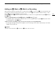
Displaying the Waveform Monitor
Press the WFM button.
• The waveform monitor window will appear at the right of the monitoring screen on external monitors
connected to one of the MON. terminals or the HDMI OUT terminal.
• You can also set [Assist. Functions] > [Waveform Monitor] > [VIDEO Output] and/or
[MON.+HDMI Output] to [On] to display the waveform monitor on the respective monitoring devices.
• Alternatively, you can press an assignable button set to [WFM: VIDEO] (optional viewfinder only), [WFM:
MON.+HDMI] (external monitors only), or [Waveform Monitor] (all monitoring devices at once) (A 127).
• You can use the [Assist. Functions] (
A
) > [Waveform Monitor] > [Position] setting to select
the position of the waveform monitor on the screen (left or right side).
Configuring the Waveform Monitor
1 Open the waveform monitor’s [Type] submenu.
[Assist. Functions] (
A
) > [Waveform Monitor] > [Type]
2 Select the desired option and then press SET.
• If you selected [Select Line], continue the procedure to set the Y coordinate of the line you wish to display.
Otherwise, skip to step 5 to change the gain.
3 From the same submenu, select [Select Line] and then press SET.
4 Enter the Y coordinate of the desired line using the keyboard screen (A 37).
• While recording, when the vertical resolution (number of horizontal lines) is 1080, you can select a value
between 0 and 1079 (1-line increments); when the vertical resolution is a value other than 1080, you can
select a value between 0 and the <vertical resolution – 2> (2-line increments).
• During playback, depending on the clip’s resolution, you can select a value from one of the following ranges.
0 to 1079 (1-line increments)
0 to 2158 (2-line increments)
0 to 3138 (2-line increments)*
* qr only.
5 From the same submenu select [Gain] and then press SET.
6 Select the desired amplification ratio and then press SET.
• If you selected [1x], the rest of the procedure is not necessary. If you selected [2x], the display range of the
waveform monitor’s Y axis will be reduced by half. Continue the procedure to select the minimum luminance
value (in %) shown on the Y axis.
7 From the same submenu select [Y Position] and then press SET.
8 Select the desired percentage and then press SET.
Options
[Line]: Sets the waveform monitor to line display mode.
[Line+Spot]: The waveform of the area in the red frame is displayed in red on top of the [Line] mode
waveform.
[Select Line]: The selected horizontal line will be displayed along with its waveform.
[Field]: Sets the waveform monitor to field display mode.