Canon NEW F-1 Service manual CANON NEW F-1 SERVICE MANUAL EXPLODED VIEWS AND PARTS LIST CANON INC.
Canon NEW F-1 Service manual Contents 1. SWITCH POSITION AND NOMENCLATURE ............................................................................................... 4 2. COVERS ................................................................................................................................................................ 6 3. FRONT PANEL UNIT ATTACHMENT AND REMOVAL .......................................................................... 10 4. FRONT BODY .......................
Canon NEW F-1 Service manual Introduction The NEW F-1 is the base of a completely new Integrated Functional System. It is based on the original F-1 but utilizing many advances in electronics, precision machining and precision optics made since the original F-1 was developed ten years ago. The following considerations should be kept in mind when repairing the New F-1: 1.
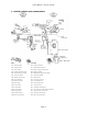
Canon NEW F-1 Service manual 1. Switch position and nomenclature Name Operation SW1 Metering Switch ON: Metering activated SW2 Release Switch ON: Starts Release sequence SW4 Count Switch OFF: Shutter exposure timing starts SW5 Winding Complete Switch OFF: Winding complete SW6 Stop-down (S.D.) Switch ON: Stopped-down (ganged with SWll1) SW7 Self Timer Switch ON: Self timer activated SW8 Battery Check Switch ON: Battery Check SWll Lens A-M Switch.
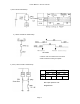
Canon NEW F-1 Service manual 1) SW12 and SW18 Relationship 2) SW16 and SW16' Relationship 1st curtain X contact must turn off after the 2nd curtain closes and before winding is complete. 3) SW11, SW6 and SW11’ Relationship SW11 SW6,1 1' Lens "A" Max. S.D. Lens "M" Max. S.D. ON OFF ON OFF ON Max: Open aperture S.D.
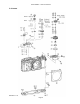
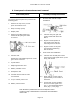
Canon NEW F-1 Service manual 2.
Canon NEW F-1 Service manual Disassembly Notes 1. Remove the smooth face screw (3) and shutter button (6) with tool (CY9-6131-000). 2. Be careful not to lose detent ball (7)-2 inside the camera. Assembly and Adjustment Notes 4. Place teflon washer (8) under the lock lever (7). Use a washer that is 0.3mm thicker than the "A" dimension shown below. (Water resistance) 3. The shutter dial cap (9) is glued in place. 4.
Canon NEW F-1 Service manual Assembly and Adjustment Notes 7. Adjust the rewind crank (22) slip torque by changing the friction washer (21). Torque Limits: 35 to 55 gcm. 8. Lubricate both sides of friction spring (20) with PL-015. 9. Hold the rewind fork. Raise the rewind crank knob and turn in the rewind direction. The clutch should engage within one half turn, 10. To install the ASA Dial, set the SV wiper wiper pin as shown and align the "1/2" on the exposure compensation dial with the index. 11.
Canon NEW F-1 Service manual Assembly and Adjustment Notes 12. SV Brush Adjustment 12.1. Set the SV (ASA.) dial to ASA 6400 -1/3. 12.2. Set the exposure compensation dial at "1". 12.3. Check the position of the brush through the P.C. terminal hole. Note: Shining the light source (a penlight or the illuminator D or M) through the loupe makes the brush position easier to see. 12.4. Look at the underside of the SV board to check if the brush if the brush is positioned as shown on the ASA 6400 -1/3 pad.
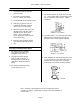
Canon NEW F-1 Service manual 3. Front panel unit attachment and removal Disassembly Notes To remove the front panel unit, remove the following parts. 1 Remove the top covers, mount apron and bottom cover. 2 Body coverings (front) 3 Beeper plate 4 Removing the Mg2 latch lever makes the AE joint gear easier to remove. Assembly and Adjustment Notes 1 1.1 Lubricate the joint gear and coupler shafts with Astro-OilMIL-G. 1.
Canon NEW F-1 Service manual Assembly and Adjustment Notes Disassembly Notes 2.4 In the order shown in figure 2, set the levers as shown in figure 3. 13. If the SV board is to be removed, remove the white cord from the P.C. Terminal. If the SV board is not going to be removed, lift the front panel and unsolder to white cord from the front panel (SW16’) end. 14. Remove the plastic foam light shields from the battery box area. 15.
Canon NEW F-1 Service manual 4.
Canon NEW F-1 Service manual Assembly and Adjustment Notes Disassembly Notes 1. To remove the main circuit board (6), the lower body flex must be moved slightly. 2. When the battery cover is removed, temporarily replace the earth (grounding) screw. 4. Clean the connector portions of the resistor board (R Board) (9) and main circuit board (6) (rear side) and apply electrolub. 5. Install the resistor board (9) into the body. Put diabond on the rear of the board around the mounting holes. 6.
Canon NEW F-1 Service manual Assembly and Adjustment Notes 8. Attach the light shield (12) and seal (13) as shown. 9. Pentaprism Contact Installation 9.1. Don't interchange the position of the left and right contacts, or reverse either of them. 9.2. Solder the leads as quickly as possible. Excessive heat will loosen the contact pins. 10. Main Flex Installation 10.1. Solder the main flex (16) at the following positions. 10.2.
Canon NEW F-1 Service manual Assembly and Adjustment Notes 11. Front Panel Lead Soldering 11.1. Put flux on the main circuit board solder lands. 11.2. Solder from the bottom up. 11.3. Dress extra lead toward the bottom as shown. Note: The thick white lead goes to the P.C. terminal. Note: Numbers in parentheses in the text correspond to circled numbers on page 12. Disassemble in normal order and reassemble in reverse order.
Canon NEW F-1 Service manual 5.
Canon NEW F-1 Service manual Assembly and Adjustment Notes Disassembly Note 1. Shutter Speed Selector 1.1. To remove the shutter speed selector (6), unsolder the black lead from SW4 and remove four screws [(6)-1 x 2 and (6)-2 x 2]. 1. The shutter speed selector (6) TV double brushes must be aligned both vertically and radially, so they will both make contact with the correct pad. 2. Clean the TV resistor board (2) and install it so that break in the pattern is at the upper right with the shutter at "A".
Canon NEW F-1 Service manual Assembly and Adjustinent Notes 4. Winding Unit (9) Installation 4.1. Lubricate the winding coupler joint with MIL-G. 4.2. Lubricate the friction surfaces of the idler gear and frame counter drive claw with Lozoid 72090. 4.3. Install with the frame counter drive claw pulled out of the way. 5. Put a little Arontite L in the Key screw (10) hole in the sprocket shaft (12) and install the screw. 6. 2nd Curtain Cam Follower (13)-3 Installation 6.1. 6.2.
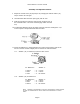
Canon NEW F-1 Service manual 6. Tungsten cable adjustment Assembly and Adjustment Notes 1. Put the knotted end of the cable into the slot in the indicator pulley. Charge the pulley one revolution and temporarily install a pin to hold it. 2. Check that the cable lies correctly in the pulley. 3. Set the shutter dial at "B". Information pulley 4. Thread the cable as shown in figure 1. 5. Remove the pin from the indicator pulley and find the spot where the "B" appears in the finder.
Canon NEW F-1 Service manual 7.
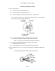
Canon NEW F-1 Service manual Disassembly Notes Be careful not to loose any of the bearing balls inside the camera. (See the facing page for the number of balls in each location.) Assembly and adjustment 1. Winding Coupler (4) 1.1 With the shutter completely wound {winding stopper engaged) , the winding coupler should be positioned as shown (10° ± 4.5° off the body centerline). 1.
Canon NEW F-1 Service manual 8. Sprocket Assembly and adjustment notes 1. Lubricate the upper and lower sprocket bushings with PL-015. 2. Adjust thrust play to 0.1 to 0.2mmm with washer (8). 3. Align the toothless section of the main gear with the stopper notch in the sprocket shaft (3) 4. Adjust thrust play of the main gear to 0.03 to 0.15mm bywasher (4). 5. Align the main gear (2) and idler gear (12) as shown below and mesh them. The protuding striker section should be as shown ±2 teeth.
Canon NEW F-1 Service manual 9. Checks and adjustments Assembly and Adjustment Notes 1. Shutter Curtains Installation 1.1. In the wound condition, the leading edge of the 2nd curtain should be from 5.4 to 5.9mm from the edge of the film aperture. 1.2. The leading edge should be parallel with the edge within 0.2mm. 1.3. In the wound condition, the trailing edge of the 1st curtain should overlap the leading edge of the 2nd curtain by 2.0 to 2.
Canon NEW F-1 Service manual Assembly and Adjustment Notes 2.2. 1st Curtain Brake Adjustment From the maximum curtain travel position, wind, release the shutter with the seesaw lever at "B", and check the difference in the position where the curtain stops and the maximum curtain travel position. It should be no more than halfa-tooth on the master gear. 1) To increase brake torque, turn the nut CW, but don't overtighten it. When you reach the point where it starts to get tight, back off 90°.
Canon NEW F-1 Service manual Adjustment Notes 4. SW4 OFF Timing 4.1 4.2 Clean the contact surface with keton. Slowly push the 1st curtain release lever in the "A" direction and note where the latch is released. Adjust the switch with the eccentric so that SW4 goes off at 0.1 to 0.2mm additional travel. 4.3 The eccentric should be adjusted so that longer side is toward the rear. 5.
Canon NEW F-1 Service manual Adjustment Notes 7. Mechanical Release Stroke Adjustment The shutter should release at 1.4±0.15mm of the shutter button stroke. Adjust with the eccentric. 8. "Bulb" Pin Adjustment Adjust so that at 1.25mm of the shutter button stroke the "bulb" pin and "bulb" lever are not touching. 9. Rewind Button Release Stroke Adjustment 9.1 Close the back cover. Set the rewind (R) button. 9.2 Adjust the eccentric so that the R button is released at 1.0±(0.
Canon NEW F-1 Service manual Adjustment Notes 11. Mechanical Shutter 11.1 Curtain Travel Time 1) Standard: 7.5±0.2ms (1/1000)(34mm slit spacing). 2) Adjustment: Spring Drum Gear 11.2 Shutter Speed (Exposure Time) 1) Adjust at 1/250 using the 2nd Curtain Release Lever (Seesaw Lever) Turning the seesaw eccentric CW increases shutter speed. 2) Adjust 1/2000 with the 2nd curtain cam follower. 3) Adjust repeating steps 1 and 2 until the best balance of all speeds is obtained.
Canon NEW F-1 Service manual Adjustment Notes 14. Maximum Aperture (AVO) Indicator 14.1 Set AVO= 2.8 (Max. Aperture Pin Height = 6.9±0.03mm) 14.2 Bend the lever (dwg.) so that the top of the red mark is positioned within the hatched area. 14.3 Check other maximum apertures. They should also fall within 0.3 to 0.5f of the same position. 15. Aperture Mask Installation and Adjustment 15.1 The distance from the "A" surface to the bottom of the mask opening is 2.42±0.03mm. 15.
Canon NEW F-1 Service manual Adjustment Notes 17. Following Needle Hidden Position 17.1 Activate the stop-down lever, with the lens on or off of "A", the following needle must not be visible. 17.2 Push the stop-down lever back into the normal position. With the lens off of "A" the following needle is visible. It must disappear when the lens is set to "A". 17.3 Adjust the hex-head eccentric (dwg.) to meet these requirements. 17.4 Following Needle Movement (Reference) 18.
Canon NEW F-1 Service manual Adjustment Notes 19. SW 18, X Sync Check and Adjustment 19.1 X Contact Check When winding from the maximum curtain travel position (MCTP), the contact separation is 0.3mm when the brake claw is on the third ratchet tooth. Also, when winding from the MCTP, the contact drive dowel must have at least 0.5mm total travel. 19.2 SW 18 Check and Adjustment 1) While winding slowly from the MCTP, adjust so that SW 18 turns on when the brake claw has traveled 2 to 2.5 teeth.
Canon NEW F-1 Service manual 10.
Canon NEW F-1 Service manual Assembly and Adjustment Note Disassembly Notes 1. SV Circuit Board (S Board)* 1. SV Ckt. Board 1.1 If the SV circuit board need only be moved out of the way: 1) Remove three screws, 2) Raising the board slightly, unsolder the timer lamp contacts. (See dwg.) 1.1 SV contact height = 3-4mm 1.2 The SV brush (wiper) must move smoothly without catching. 2. Put the opening in the C ring toward the front of the camera. 3. Before installing the SV ckt.
Canon NEW F-1 Service manual Assembly and Adjustment Notes 5.1 Make sure the connector legs are correctly aligned with the solder lands on the main ckt. board and then solder them together. 6. When installing the meter/indicator unit (5) + (6), make sure the meter needle clears the red mark on the AVC indicator (7). 7. Exposure Flex Installation 7.1 Before connecting the exposure flex to the meter indicator unit (5&6) or the SC ckt.
Canon NEW F-1 Service manual 11.
Canon NEW F-1 Service manual Assembly and Adjustment Notes Disassembly 1. The mounting screw (7}-l for Mg2 is hidden under the lead solder connection. 2. Mg2 Lead is a single solid, lead. Take care not to kink the cable. Assembly and Adjustment Notes 3. The shorter hook of the main diaphragm charge lever spring (11)-2 hooks at the diaphragm release drive lever (Matsuba lever) -which is part of the diaphragm charge lever (11). 1. Lower body Flex 4.
Canon NEW F-1 Service manual Assembly and Adjustment Notes 4.3 Winding Stopper and Charge Lower Check After installing (15) through (17) check the following points. 1) Winding Latch Overcharge: 0.3mm or more 2) When the SW5 pin is moved, the stopper lever must move smoothly without catching. Note: Numbers in parentheses in the text correspond to circled numbers on page 34. Disassemble in normal order and reassemble in reverse order.
Canon NEW F-1 Service manual Assembly and Adjustment Notes 5. Mirror Charge Timing 5.1 Wind until the hook (see dwg.) on the mirror mechanism side of the front panel is set (The hook is easier to see if the battery box is removed). 5.2 In this condition check the position of the charge lever and the mirror latch lever. It should be as shown. To adjust, loosed the lever screw and move the lever. 5.3 Post-Adjustment Checks 1) At maximum charge the separation between the two levers (above step) is 0.
Canon NEW F-1 Service manual 12.
Canon NEW F-1 Service manual 13.
Canon NEW F-1 Service manual Assembly and Adjustment Notes Disassembly Notes 1. Mg3 1.4 1.1 To remove Mg3 (1), remove screw (1)-1. Open the armature and remove (l)-2 using a small crossrecess screwdriver. Remove one more screw (l)-3 and the magnet can be removed. 1.2 The armature is bonded to its base with silicone rubber. 1.3 Apply current (8mA) to close the the magnet. In this condition, run silicone KE 471RTV into the crack between the armature and armature lever, and let dry about 12 hours.
Canon NEW F-1 Service manual Assembly and Adjustment Notes 4. 2nd Curtain Latch Adjustment 4.1 Unsolder the data back direct contact and run keton (MEK) in around it. 4.2 Push the contact out from the inside. 4.3 Push on the armature lever and check the latch mesh. (Fig. 1) 4.4 Adjust the overlap to the limit shown in figure 2. 4.5 Stake the setscrews with Arontite R. 4.6 Apply Astro-oil to the latch surface. 5. 2nd Curtain Latch Operatic Check 5.
Canon NEW F-1 Service manual 14. Electrical adjustments Introduction and Contents There are many electrical checks and adjustments for this camera, but they need not all be checked every time work is performed on the camera. The following table is a combined table of contents and guide to pertinent checks depending on the type of repair performed. Adjustment Type of repair Normal Adjustment 1. Offset IC-1 Replaced Main CKT Replaced AV METER Replaced Do 2. R OSC2 (R43) Check 3.
Canon NEW F-1 Service manual Assembly and Adjustment Notes 1. Offset 1.1 Offset Voltage Check 1) Unsolder one end of the RTC resistor 2) Short pins 9 and 11 . 3) Measure the voltage from pin 10 to Gnd. (V1). 4) Measure the voltage from pin 11 to Gnd. (V2). 5) If Vl-V2= 0±lmV, adjustment is not necessary. 1.2 Offset Adjustment 1) If difference is greater than lmV, adjust the offset. 2) Remove Rl or R2 and install a 200kohm variable resistor in its place.
Canon NEW F-1 Service manual Assembly and Adjustment Notes 2.2 (R43) Adjustment If the oscillator is not within limits, proceed as follows. 1) Remove the ROSC resistor and replace it temporarily with an approximately 200kohm variable resistor. 2) Adjust the variable resistor until the shutter speed is within limits. Remove the variable and measure it. Install a fixed resistor with a resistance as near as possible to the resistance of the variable. 3) Recheck with the new resistor installed. 3.
Canon NEW F-1 Service manual Assembly and Adjustment Notes Shutter speed 1/2000 1/1000 1/500 1/250 1/125 1/60 1/30 1/15 1/8 TVS VR3 Output 11 10 9 8 7 6 5 4 3 1.3461*VC 1.2692*VC 1.1923*VC 1.1153*VC 1.0384*VC 0.9615*VC 0.8846*VC 0.8076*VC 0.7307*VC Shutter speed ¼ ½ 1” 2” 4” 8” R B TVS VR3 Output 2 1 0 -1 -2 -3 0.6538*VC 0.5769*VC 0.5000*VC 0.4230*VC 0.3461*VC 0.2692*VC 0 0 5. V AVO Output Check (Checkpoint Fig. 3 #1) 5.1 Check the output at 1 (Fig.
Canon NEW F-1 Service manual Assembly and Adjustment Notes 6.3 Reference 7. VR GAIN (VR 2) Adjustment 7.1 Mount the tool standard FD5C/1.4, standard focusing screen (PE) and pentaprism. 7.2 Check the output at #3 (Fig. 3) with the light source at EV 9 and EV 15 and record the values as V EV9 and V EV15. 7.3 Adjust VR 2 so that the difference between V EV9 and V EV15 is equal to VC/30x6 (±2mV) 8. VR AV (VR 7) Level Adjustment 8.
Canon NEW F-1 Service manual Assembly and Adjustment Notes 9. VR TV (VR 6) Level Adjustment 9.1 Set the aperture to f/5.6 (AVS=5), the shutter speed to "A" and the EV Tester light source to EV12. 9.2 Release the shutter and adjust VR6 so the exposure tester reads 0 ±.0.1 EV 9.3 Another method is to check the voltage (V TV) at Fig. 4 #2. It should be: V TV = 1.0433 (VC) * 5mV. 10. Battery Check Mode V AV Check When E1 (measured at SV ckt. board) is 3.
Canon NEW F-1 Service manual Assembly and Adjustment Notes 13. R MTV2 (JUS) Adjustment 13.1 Check the internal resistance of the ammeter ''A". 13.2 Add a dummy resistor to make the interval resistance + dummy resistor = 330ohm. 13.3 Set the shutter to "A" and the aperture to f/5.6 (AV5). 13.4 Set the light source to EV 12. 13.5 Install an approximately 500ohm variable resistor as shown and adjust for a current of 488.25 µA ±7µA. 13.6 Remove the variable resistor.
Canon NEW F-1 Service manual Assembly and Adjustment Notes 14. R AE Selection and Installation 14.1 Set the light source to LV 12.6 (819.6), the aperture to f/8 (AV 6) and shutter to 1/125 (TV 7). Note: If light source cannot be set to 12.6, set the aperture to f/6.7 (AV 5.5) and the light source to LV 12. 14.2 Install a 100kohm variable resistor. 14.3 Adjust the variable resistor so that the "IN" voltage is equal to VC ± 2mV. 14.
Canon NEW F-1 Service manual 15.
Canon NEW F-1 Service manual Disassembly Notes Assembly and Adjustment Notes 2.2 Check that the height of the pin in the relaxed position is 5.7± 0.05mm below the mount surface. 2.3 The pin (8) must work smoothly. 1. Do not bend the brush contacts on VR AOAC (VR 9) wiper (3). 2. To remove the A Mode (switch) assy. (22), first remove spring holder (21), spring (20) and the mirror start latch (see dwg.). 3. G Ring (6) 3.
Canon NEW F-1 Service manual Assembly and Adjustment Notes 5.4 Attach spring (10) to hooks of (15) and (21) and spring (5) to hooks of (13) and (7). 5.5 Check that the stop-down slide operates normally. 6. Lubricate the cam surface of the stop-down lock lever with UTLM-10. 7. Lubricate the A-M pin (23) with FLA. 8. A-M Changeover 8.1 Check the A-M pin after installing the A Mode Assy. (22). 1) A-M pin height (Std: Mount surface) : 0 0.05mm. 2) A-M pin returns smoothly and positively.
Canon NEW F-1 Service manual Numbers 1-9 Page 53
Canon NEW F-1 Service manual Assembly and Adjustment Notes 4. Following needle lever 1. Lubricate all lever pivot shafts with MIL-G. 2. Lubricate the friction surfaces (///// marks) with Lozoid 72090. Lubricate the slots of the brake lever [p/o the mirror charge lever (4)-4] with MILG. 4.1 Slip the end of the following needle lever (7) under the resistor section of AE unit. 4.2 The bottom end of lever (7) should be engaged with the lowest part of lever A and shown below. 4.
Canon NEW F-1 Service manual Numbers 1-13 Page 55
Canon NEW F-1 Service manual Assembly and Adjustment Notes 1. Mirror 1.1 Lubricate the mirror hinge with UTLM-10. 1.2 Mirror (1) thrust play should be between 0.05 to 0.25mm. Adjust collar (1)-3. 1.3 Mirror (1) must move smoothly under its own weight. 2. Pentaprism Contacts 2.1 Soldering time to the pentaprism contacts (2) and (3) should be kept as short as possible to avoid loosening of the contacts in their plastic seats.
Canon NEW F-1 Service manual 7. Light Shields 7.1 Both light shields (10) and (14) have heat-sealed edges to prevent fraying, 7.2 Light shield (14) should stand away from the frame light shield (13) by 2 to 3 mm. Heat it with a soldering iron to shape it correctly.
Canon NEW F-1 Service manual Assembly and Adjustment Notes 1 1st Curtain Release (Mirror Release) 1.1 Move the mirror charge lever in the direction shown at the right. 1.2 Move the lever until the mirror is at midposition, then set the 1st curtain release lever as shown. 1.3 Slowly return the mirror charge lever and note the position of the mirror when the 1st curtain release releases. 1.4 The correct position for the 1st curtain release lever to release is when the mirror is 1.5 to 4.
Canon NEW F-1 Service manual Assembly and Adjustment Notes 4. VR AOAC (VR9) Wiper Adjustment 4.1 In the relaxed position (AVO=5.6) the pin height* should be 5.7 ± 0.05mm. *: Pin height is repair jargon. In the case of lenses, it is correct, since the pin protrusion above the standard mount surface if measured. In the body, the opposite is true. The pin height is a measure of how much the pin is recessed below the mount standard surface. 4.2 Set the max. aperture pin to the f/2.8 height.
Canon NEW F-1 Service manual Assembly and Adjustment Notes 6.2 Check the brush position also at AV=0, AV=4 and AV=8 also. The limit is ±0.2 AV. (each pattern element is 0.1AV). Note: Some R AV boards have circular marks indicating full step intervals and others have triangular marks. 6.3 After the adjustment is finished, stake the mounting screw with diabond. 7. Coupling Adjustment Plate Adjustment 7.1 Set the tool standard lens to "A". 7.2 Loosen the coupling lever screw. 7.
Canon NEW F-1 Service manual 16.
Canon NEW F-1 Service manual Assembly and Adjustment Notes 1. The thinner side of the eyepiece mask (6) goes to the right. 2. Eyepiece Frame (7) 2.1 The plastic foam light shield in eyepiece frame (7) should not be visible. 2.2 The notch in the frame goes down. 3. Full the space between the accessory cover (1) and the diecast pentaprism box with black diabond. 4. Apply oil retardant OBF-10 around the junction of the die casting and eyepiece lens. (Water resistance) 5.
Canon NEW F-1 Service manual Assembly and Adjustment Notes 7. Assemble the contacts (16) and (18) so contact I (18) is under contact II (18). 8. After installing the accessory shoe mounting plate (23), apply black diabond all around the joint with the prism cover so no crack is left open. (Water resistance) 9. Pentaprism Cover, Lead Dress 9.
Canon NEW F-1 Service manual Numbers 1-39 Page 64
Canon NEW F-1 Service manual Assembly and Adjustment Notes 1. The eyepiece shutter is assembled as shown. 2. Pentaprism Play Removal 2.1 Select the correct spacer (a) for the left side. 2.2 Select the correct spacer (b) for the right side. (Both spacers are available in several sizes.) 2.3 Bond the spacers in place with black diabond. 3. The rail pressure pins (15), (17) and (26) have to be installed in the correct direction. 4.
Canon NEW F-1 Service manual 17. Moisture Resistant Treatment Apply moisture-proofing (Tuffy TF-1156) at the points indicated by hatching. 1. On the body at the SW 18 mounting position. 6. Pentaprism Contacts (X contact) 2. On the body at the SW 12 mounting position. 7. Top Cover (Right) Approx. 30mm 3. SW 18 assembly (To the contact base) 4. Timer lamp contact assy. 8. MD contact (back side) Cover completely 5. Main flex.
Canon NEW F-1 Service manual 9. MD Contact (Front side) 13. Pentaprism Contacts (X contacts) 10. MG 3 Lead connections 14. Capasitor CE1 (SV Board) 11. Main flex front side soldering (1) Soldering points on front of board. (2) Rear Side: Capacitor leg and hole - Liberal amount 12. SW 1 15.
Canon NEW F-1 Service manual 18. Water resistant treatment 1. Inject silicone in the space between the front panel and the lower body "obi" (band). 4. Use the teflon washer in the release lock lever. 2. Put the rubber seal in the groove and apply silicone (KE-347B) on it. 5. Place the teflon washer in the shutter dial seat under the shutter dial. 3. Apply grease (GE-C9) between the shutter button'assembly and the release lock ring. 6. Put two types of teflon washers in the ASA dial.
Canon NEW F-1 Service manual 7. Place the rubber seal between the front panel and body die castings. 11. Lift the exposure flex out of the way and put silicone (KE 347B) in the space shown below. 8. Bond the following needle adjustment hole cover in place (1). 9. Insert the SW 18 conductive rubber cover (2). 12. Put silicone (KE 347B) in the crack around the battery cover. 10. Install the water seals in the base cover.
Canon NEW F-1 Service manual 19. Shutter speed variations (Based on +/- EV) T=2-n EV \ 2000 11 1000 10 500 9 250 8 125 7 60 6 30 5 15 4 8 3 4 2 2 1 1” 0 2” -1 4” -2 8” -3 0 500 0.691 1.381 2.762 5.524 11.05 22.10 44.19 88.39 176.8 353.6 707.1 1414.2 2828 5657 11314 0.450 0.667 1.334 2.668 5.336 10.67 21.34 42.69 85.38 170.8 341.5 683.0 1366.0 2732 5464 10928 0.400 0.644 1.289 2.577 5.154 10.31 20.62 41.23 82.47 1R4.9 329.9 659.8 1319.
Canon NEW F-1 Service manual 20. Service tools list (Ref. No. C1-0751) TEST EQUIPMENT (USE) (NAME OF TEST EQUIPMENT) 1. Shutter Shutter Tester (Model 7J-18C) or PA-16 Transistorized Shutter Tester or Simplified Shutter Tester 2. Exposure Meter 2.1 D.C Voltage Tester (Digital Tester Model VOAC 7 07 or VOAC 77) ( Must measure to 1mV) 2.2 Standard Brightness Checker (CdS) or Canon Luminance Meter (S.B.C) 2.3 Oscilloscope (Electric Circuit General Check) 3.
Canon NEW F-1 Service manual SMALL HAND TOOLS Canon NEW F-1 (C12-0751) Place of use CY9-6129-000 Rewind Shaft CY9-6130-000 AVO Wiper CY9-6131-000 Winding Lever Screw, Shutter Button Ring CY9-6132-000 ASA Dial Nut CY9-6133-000 2nd Curtain Latch CY9-6134-000 Rewind Knob Pin-face Screw CY9-6135-000 Pentaprism Button Holder CY9-6125-000 Charge lever Shaft CY9-6126-000 1st.
Canon NEW F-1 Service manual CY9-6127-000 Indicator Cable CY9-6128-000 VR TV Circuit Board CY9-6136-000 Shutter Adj. CY9-6137-000 P.C.
Canon NEW F-1 Service manual 21. Troubleshooting charts Series 1: Shutter Will Not Release 1.1 Meter Always ON 1.2 Miscellaneous 1.3 No V Batt 1.4 No E 1 1.5 No Vc 1.6 No KVc 1.7 Sw 2 Check 1.8 Sw 4 Check 1.9 Sw 5 Check 1.10 Sw 11 Check 1.11 Mg 3 Check 1.12 Mg 3 Check 1.13 No Clock Pulse Note: All circuits are coated with Tuffy TF-1156 which must be penetrated to make contact with the probe.
Canon NEW F-1 Service manual 1.1 Meter always on *: Check for after effects (stains, etc.) of moisture condensation.
Canon NEW F-1 Service manual 1.
Canon NEW F-1 Service manual 1.2 Miscellaneous (contd.
Canon NEW F-1 Service manual 1.
Canon NEW F-1 Service manual 1.
Canon NEW F-1 Service manual 1.5 No Vc (Correct Vc : 1.3V +/- 50mV) 1.
Canon NEW F-1 Service manual 1.
Canon NEW F-1 Service manual 1.
Canon NEW F-1 Service manual 1.9 SW 5 Check 1.
Canon NEW F-1 Service manual 1.
Canon NEW F-1 Service manual 1.11 Mg 3 Check (contd.
Canon NEW F-1 Service manual 1.
Canon NEW F-1 Service manual 1.12 Mg 2 Check (contd.
Canon NEW F-1 Service manual 1.
Canon NEW F-1 Service manual 22. Parts Lists CANOW NEW F-1 SERVICE PARTS POLICY 1. THE POLICY OF CAMERA SERVICE, TOKYO, IS TO STOCK ALL PARTS NECESSARY TO EFFECT EFFICIENT ECONOMICAL SERVICE. IT IS NEITHER NECESSARY NOR TECHNICALLY FEASIBLE TO STOCK SEPARATELY EVERY PART THAT GOES INTO EACH PRODUCT. IN ESTABLISHING THE SPARE PARTS LIST, WE CONSIDER REPAIR DIFFICULTY, LABOR COST, SPECIAL TOOL REQUIREMENTS AND INDIVIDUAL PARTS Vs. ASSEMBLED UNIT COST TO DETERMINE IN WHICH FORM PARTS WILL BE STOCKED. 2.
Canon NEW F-1 Service manual REF.NO.C12-0751 CONTENTS EXTERNAL PARTS REWIND CRANK & BACK COVER BACK COVER METER/INDICATOR & REWIND SHUTTER SPEED SELECTOR FRONT PANEL UNIT & MAIN P.C.B MIRROR ASSY & LIGHT SHIELDS AE RESISTOR MAX. APERTURE CORRECTION UNITS ...
Pg.1 PARTS LIST REF.NO.C12-0751 NEW PARTS NO.
Pg.2 PARTS LIST REF.NO.C12-0751 NEW PARTS NO. CA1-1908-000 CA1-2090-000 CA1-2096-000 CA1-2097-000 CA1-2098-000 CLASS QTY DESCRIPTION B 1 COVER, BASE D 1 WINDOW E 1 LEVER, LOCK C 1 LATCH, SAFETY E 1 CONE CA1-2102-000(XXX) CA1-2103-000 CA1-2108-000 CA1-2112-000 CA1-2113-000 D D C B B 1 1 1 1 1 WASHER NUT WASHER KNOB, REWIND CRANK SCREW CA1-2148-000 CA1-2151-000 CA1-2152-000 CA1-2153-000 CA1-2401-000 D A A B C 1 1 1 1 1 SPACER CAP, M.D.
Pg.3 PARTS LIST REF.NO.C12-0751 NEW PARTS NO.
Pg.4 PARTS LIST REF.NO.C12-0751 NEW PARTS NO. CA1-2073-000 CA1-2074-000 CA1-2075-000 CA1-2076-000 CA1-2077-000 CLASS QTY DESCRIPTION E 1 HOLDER, REWIND SHAFT C 1 FORK, REWIND E 1 OPENER, BACK COVER D 1 CONTACT D 1 SEAL, CONNECTOR CA1-2084-000 CA1-2246-000 CA1-2249-000 CA1-2250-000 CA1-2255-000 E E E D E 1 1 1 1 2 HOOK CLAW, FINDER INFORM.
Pg.5 PARTS LIST REF.NO.C12-0751 NEW PARTS NO.
Pg.6 PARTS LIST REF.NO.C12-0751 NEW PARTS NO. 13-9744-000 CA1-2027-000 CA1-2046-000 CA1-2058-000 CA1-2061-000 CLASS QTY DESCRIPTION D 1 CUSHION C 1 PLATE, ACCESSORY E 1 LEVER, M.E. SET E 1 PLATE, POSITION SET E 1 CUSHION CA1-2062-000 CA1-2063-000 CA1-2064-000 CA1-2065-000 CA1-2066-000 E C E E E 1 1 2 1 1 HOLDER, REWIND SHAFT TERMINAL, M.D.
Pg.7 PARTS LIST REF.NO.C12-0751 NEW PARTS NO.
Pg.8 PARTS LIST REF.NO.C12-0751 NEW PARTS NO. CA1-2029-000 CA1-2273-000(XXX) CA1-2289-000 CA1-2292-000 CA1-2315-000 CLASS QTY DESCRIPTION E 1 STUD E 1 CUSHION D 1 PIN, MAX.APERTURE CORRECTION D 1 INSULATOR E 1 WASHER CA1-2318-000 CA1-2325-000 CA1-2334-000 CA1-2335-000 CA1-2387-000 E D E D D 1 1 1 1 1 SHAFT, CORRECTION LEVER LEVER, COUPLING ADJ. WASHER, SPRING INSULATOR WASHER CA1-2447-000 CA1-5001-000 CF1-0773-000 CF1-0774-000 CF1-0775-000 D E E E E 1 2 1 1 1 SCREW, MAX.APERTURE CORRECT.
Pg.9 PARTS LIST REF.NO.C12-0751 NEW PARTS NO.
Pg.10 PARTS LIST REF.NO.C12-0751 NEW PARTS NO.
Pg.11 PARTS LIST REF.NO.C12-0751 NEW PARTS NO.
Pg.12 PARTS LIST REF.NO.C12-0751 NEW PARTS NO.
Pg.13 PARTS LIST REF.NO.C12-0751 NEW PARTS NO.
Pg.14 PARTS LIST REF.NO.C12-0751 NEW PARTS NO.
Pg.15 PARTS LIST REF.NO.C12-0751 NEW PARTS NO.
Pg.16 PARTS LIST REF.NO.C12-0751 NEW PARTS NO.
Pg.17 ELECTRIC PARTS LIST REF.NO.C12-0751 NEW SYMBOL PARTS NO. CLASS QTY DESCRIPTION REMARK IC1 R1 R1 R1 CY4-0055-000 CH4-0055-000 VR9-1103-000 VR9-1109-000 VR9-1367-000 D C E E E 1 1 1 1 1 RESISTOR, HIGH VOLTAGE IC RESISTOR RESISTOR RESISTOR 50 OHM 1/8W T2682A 33KOHM 1/8W 56KOHM 1/8W 24.
Pg.18 ELECTRIC PARTS LIST REF.NO.C12-0751 NEW SYMBOL RMTV RMTV RMTV RMTV RMTV PARTS NO.
Pg.19 ELECTRIC PARTS LIST REF.NO.C12-0751 NEW SYMBOL R42 R42 R42 R42 R42 R42 R42 R42 R42 RTSC Tr2 VR2 PARTS NO.