
Service Manual
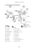
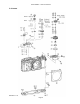
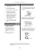
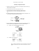
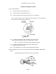
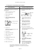
Table Of Contents

Canon NEW F-1 Service manual
Page 10
3. Front panel unit attachment and removal
Disassembly Notes
To remove the front panel unit, remove the
following parts.
1 Remove the top covers, mount
apron and bottom cover.
2 Body coverings (front)
3 Beeper plate
4 Removing the Mg2 latch lever
makes the AE joint gear easier
to remove.
5 AE Joint Gear
Position the main diaphragm lever so the
gear can be removed.
6 Tripod Socket
7 Diaphragm Stricker lever
8 Battery Chamber Cover
9 Pentaprism rails
10 Unsolder eleven leads to main
circuit board.
11 X sync contact yellow cord
12 Battery Check contact
Assembly and Adjustment Notes
1 AE Joint Gear and AE Coupler
Installation
1.1 Lubricate the joint gear and
coupler shafts with Astro-Oil-
MIL-G.
1.2 Align the raised portion of
the coupler gear with the
mounting screw as shown.
1.3 Align the mark on the joint
gear with the positioning
hole as shown.
2 Front Panel Unit Installation
2.1 Lubricate the marked parts of the
mirror charge and signal levers (in the
body) with Lozoid.
2.2 Wind until the curtain edge is
approximately in the center of
the frame.
2.3 In this semi-wound condition,
do not move the signal lever
(Fig. 1) or Intermediate signal
lever (Fig. 4, next page).
Note: Numbers in parentheses in the text correspond to circled
numbers on page 6. Disassemble in normal order and reassemble in
reverse order.