
Service Manual
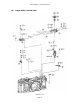
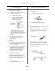
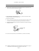
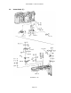
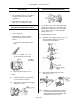
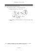
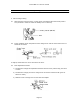
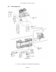
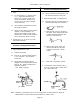
Table Of Contents

Canon NEW F-1 Service manual
Page 32
Disassembly Notes
1. SV Circuit Board (S Board)*
1.1 If the SV circuit board need only be
moved out of the way:
1) Remove three screws,
2) Raising the board slightly,
unsolder the timer lamp
contacts. (See dwg.)
By taking these steps, the SV
board can be removed from the
rewind shaft without disconnecting
it from the main and exposure
flexs.
1.2 To change the SV ckt. board,
unsolder it from the main and
exposure flex.
2. Meter Unit
2.1 Before removing the meter unit (6)
fix the information pulley with a pin
at one turn change.
2.2 Move the meter needle in the normal
deflection direction and the AVO
indicator (7) toward the penta-rail
so the meter can be removed
without the needle catching.
3. Exposure Flex (EXP FLX) *
The exposure flex cannot be removed
without disconnecting the SV Ckt.
board (4) and the meter/indicator unit
(5) & (6) must be disconnected.
*: ( ) indicate abbreviations used on
Electrical Diagrams.
Assembly and Adjustment Note
1. SV Ckt. Board
1.1 SV contact height = 3-4mm
1.2 The SV brush (wiper) must move
smoothly without catching.
2. Put the opening in the C ring toward the
front of the camera.
3. Before installing the SV ckt. board, clean
the main ckt. board contact and apply
electrolub.
4. Don't depress the rewind shaft (10) too
far when the SV ckt. board is installed.
5. Using an installed flex as a guide, bend
the main flex as shown.