
Service Manual
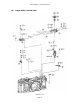
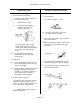
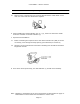
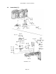
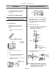
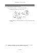
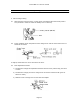
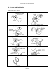
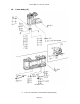
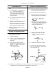
Table Of Contents

Canon NEW F-1 Service manual
Page 33
Assembly and Adjustment Notes
5.1 Make sure the connector legs are correctly aligned with the solder lands on the
main ckt. board and then solder them together.
6. When installing the meter/indicator unit (5) + (6), make sure the meter needle
clears the red mark on the AVC indicator (7).
7. Exposure Flex Installation
7.1 Before connecting the exposure flex to the meter indicator unit (5&6) or the SC
ckt. board, put it through the body opening (Once attached, it will not fit).
7.2 Apply flux to the marked areas and solder. Soldering time should be somewhat
longer than normal.
8. Even when moved quite slowly, the AVO Indicator (7) should move smoothly.
Note: Numbers in parentheses in the text correspond to circled numbers on page 31.
Disassemble in normal order and reassemble in reverse order.