
Service Manual
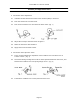
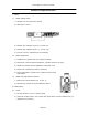
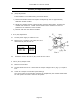
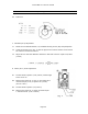
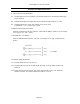
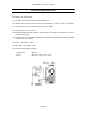
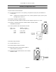
Table Of Contents

Canon NEW F-1 Service manual
Page 43
Assembly and Adjustment Notes
1. Offset
1.1 Offset Voltage Check
1) Unsolder one end of the RTC resistor
2) Short pins 9 and 11 .
3) Measure the voltage from pin 10 to Gnd. (V1).
4) Measure the voltage from pin 11 to Gnd. (V2).
5) If Vl-V2= 0±lmV, adjustment is not necessary.
1.2 Offset Adjustment
1) If difference is greater than lmV, adjust the offset.
2) Remove Rl or R2 and install a 200kohm variable resistor in its place.
3) Adjust the variable until the difference is less than 1mV.
4) Remove the variable and read its resistance.
5) Pick a fixed resistor closest to the variable resistors value
and install it.
1.3 Offset Post-Adjustment Procedure
1) Remove the short between pins 9 and 11.
2) Resolder the resistor RT leg unsoldered in Step 1
2. R OSC2(R43)
2.1 Check
1) Set the camera to 1/2 sec. shutter speed.
2) Check the shutter speed. If it is within the range 490 to 510 mS (500ms±2%), no
adjustment is necessary.