
Service Manual
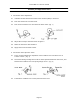
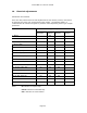
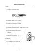
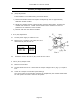
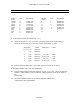
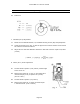
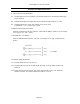
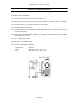
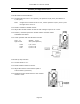
Table Of Contents

Canon NEW F-1 Service manual
Page 44
Assembly and Adjustment Notes
2.2 (R43) Adjustment
If the oscillator is not within limits, proceed as follows.
1) Remove the ROSC resistor and replace it temporarily with an approximately
200kohm variable resistor.
2) Adjust the variable resistor until the shutter speed is within limits. Remove the
variable and measure it. Install a fixed resistor with a resistance as near as
possible to the resistance of the variable.
3) Recheck with the new resistor installed.
3. R TC (R6) Adjustment
3.1 Set the power supply so V BAT is 5.0V.
3.2 Measure VC (1.3 50mV). The value of R TC is
determined by the value of VC.
3.3 Install the correct value R TC (R6) on the SV ckt. board.
4. VR TV (VR 3) Output Check
4.1 Measure VC and KVC.
4.2 Set the shutter dial to."A". Check that the output voltage of VR 3 (Fig, 3) is equal to
KVC.
4.3 Check VR 3 output at all shutter speed settings.
The correct value for each shutter speed is VC multiplied by the number listed below
for each speed. The limit is 15mV for all speeds.
VC(v) RTC
1.25-1.285
1.285-1.315
1.315-1.350
2.05kohm
2.00kohm
1.96kohm