
Service Manual
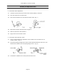
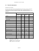
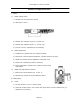
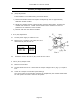
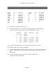
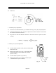
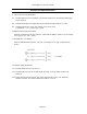
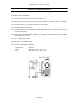
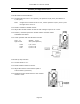
Table Of Contents

Canon NEW F-1 Service manual
Page 45
Assembly and Adjustment Notes
Shutter
speed
TVS VR3 Output Shutter
speed
TVS VR3 Output
1/2000 11 1.3461*VC ¼ 2 0.6538*VC
1/1000 10 1.2692*VC ½ 1 0.5769*VC
1/500 9 1.1923*VC 1” 0 0.5000*VC
1/250 8 1.1153*VC 2” -1 0.4230*VC
1/125 7 1.0384*VC 4” -2 0.3461*VC
1/60 6 0.9615*VC 8” -3 0.2692*VC
1/30 5 0.8846*VC R 0
1/15 4 0.8076*VC B 0
1/8 3 0.7307*VC
5. V AVO Output Check (Checkpoint Fig. 3 #1)
5.1 Check the output at 1 (Fig. 3) for each maximum aperture pin height (AVO). It
should be the produce of VC times the number listed below +/-4mV.
AVO (f/No.)
•>
V AVO AVO (f/No.) V AVO
0.5 (1.2) 1.225*VC
1 (1.4) 1.250*VC
2 (2.0) 1.300*VC 1.7 (1.8) 1.285
3 (2.8) 1.350*VC 2.633 (2.5) 1.332
4 (4.0) 1.400*VC 3.6 (3.5) 1.380
5 (5.6) 1.450*VC 4.333 (4.5) 1.4 17
5.2 Activate the stop-down slide. The V AVO value is the same as for AVO 5.
6. SV (ASA) Resistor (VR1) ASA 100 Positioning
6.1 Turn the ASA resistor so that the output at #2 (Fig. 3) is 1.2VC. This is the ASA 100
position. If the position is not pre-marked, make a reference mark on the edge of
the
resistor disk.
6.2 The VR SV positioning tool can be used to hold the resistor disk
in position for other adjustments.