
Service Manual
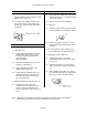
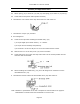
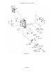
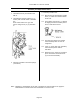
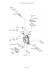
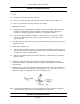
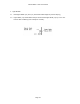
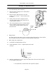
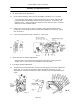
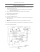
Table Of Contents

Canon NEW F-1 Service manual
Page 51
Disassembly Notes
1. Do not bend the brush contacts on VR
AOAC (VR 9) wiper (3).
2. To remove the A Mode (switch) assy.
(22), first remove spring holder (21),
spring (20) and the mirror start latch
(see dwg.).
Assembly and Adjustment Notes
1. VR AOAC Lever
1.1 Check that both contacts of the VR
AOAC (VR 9) wiper brush (3) are
the same height and the brushes
work smoothly
without catching.
1.2 Lubricate the shaft hole of (3) and
washer (4) with MIL-G.
1.3 Clean the pattern surface of VR
AOAC resistor board (9).
1.4 Check that the VR AOAC wiper (3)
operates smoothly even when the
maximum aperture correction pin
(8) is moved slowly.
2. Maximum Aperture Correction Pin (8)
2.1 Lubricate the max. aperture
correction pin (8) and the hole it
works in with a small amount of
FLA (not enough to come out of the
hole).
Assembly and Adjustment Notes
2.2 Check that the height of the pin in the
relaxed position is 5.7± 0.05mm below
the mount surface.
2.3 The pin (8) must work smoothly.
3. G Ring (6)
3.1 Install G ring (6) in the direction shown
and insure that it is completely seated.
3.2 After installing the G ring (6). Check
that the following needle holder works
smoothly.
4. Do not forget the mylar washers (9)-2
when installing the VR AOAC board (9).
5. Diaphragm Closing Slide (15)
5.1 Do not forget collar (12) when
assembling slides (15) and (13) with
screw (11).
5.2 Lubricate the slide (15) and A Mode
slide (13) friction surfaces with UTLM-
10.
5.3 When installing the slide (15), make
sure that the tapered pin on stop-down
lock lever (19) fits as shown below.
Note: Numbers in parentheses in the text correspond to circled numbers on page 50.
Disassemble in normal order and reassemble in reverse order.