
Service Manual
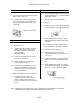
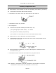
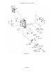
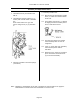
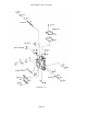
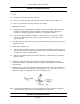
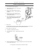
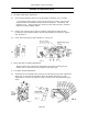
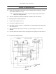
Table Of Contents

Canon NEW F-1 Service manual
Page 52
Assembly and Adjustment Notes
5.4 Attach spring (10) to hooks of (15) and (21) and spring (5) to hooks of (13) and (7).
5.5 Check that the stop-down slide operates normally.
6. Lubricate the cam surface of the stop-down lock lever with UTLM-10.
7. Lubricate the A-M pin (23) with FLA.
8. A-M Changeover
8.1 Check the A-M pin after installing the A Mode Assy. (22).
1) A-M pin height (Std: Mount surface) : 0 0.05mm.
2) A-M pin returns smoothly and positively.
3) A-M switch is on when A-M pin is 0.4 to 0.6mm below mount surface.
8.2 With the lens on "A" the lock pin of (19) must not release.
8.3 Check that SW II' is on when the stop-down slide is in the normal position and off
when the slide is extended.
8.4 When installing the A Mode Assy. (22), the A-M change lever should be over the
intermediate lever (18).
9. Lubricate the friction surfaces of intermediate lever (24) with UTLM-10.
Note: Numbers in parentheses in the text correspond to circled numbers on page 50.
Disassemble in normal order and reassemble in reverse order.