FAXPHONE L75 SERVICE MANUAL Canon
I. PREFACE This manual is based on the following manuals, and only includes differences between LASER CLASS 1060P and FAXPHONE L75. HY8-19AU-000 HY8-39AR-000 HY8-89AT-000 LASER CLASS 1060P SERVICE MANUAL, Rev.0 LASER CLASS 1060P CATALOG, Rev.0 LASER CLASS 1060P CIRCUIT DIAGRAM, Rev.0 II. CONTENTS CHAPTER 1 : POINTS OF DIFFERENCE FROM THE ORIGINAL MACHINE This chapter explains the differences between this machine and the original one.
CHAPTER 1 POINTS OF DIFFERNECE FROM THE ORIGINALMACHINE 2
1. Parts change For details of any change in parts numbers, see the Parts Catalog. 2. Specification change Canges have been made to the electrical circuitry, and the functions of the NCU board have been integrated with those of the SCNT board. In this Service Reference Manual, detailed explanations of the electrical circuitry have been omitted (to respect the decision not to disclose detailed information in technical documentation, e.g., on ICs).
Interface specifications (FAXPHONE L75) interface USB only Support software Windows 98/Me/2000/XP Winsows 95/NT4.0 (Not support) Windows 95 Windows 98 Windows NT 4.0 Windows 2000 Windows Me Windows XP FAX-L290 Suite USB I/F not supported conditionally supported* not supported conditionally supported* conditionally supported* conditionally supported* *: A USB connection applies to Windows XP/Me/2000 pre-install models and to pre-install models upgraded to Windows XP/Me/2000 from Windows 98 or later.
7. Error codes and recovery methods As for the descriptions of causes of and actions for error codes, only those items to which changes have been made because of the use of different connector numbers are indicated. #001 [TX] Paper jam Cause: The document jammed in the fax machine. Solutions: Remove the document and transmit/copy again. Cause: The document width size or thickness does not meet the standards.
#003 [TX/RX] Copy page transmission time over Cause: One page of the document was longer than 39.4 inches (1 meter) or transmission/copying took longer than the regulated time (32 minutes). Solutions: (1) Use a copy machine to copy the document onto serveral shorter page, then tranmit/copy. (2) Raise the page timer value with Service Data #1 SSSW SW12. Cause: Reception took longer than the regulated time (32 minutes).
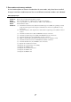
##322 [RX] Fixing heater temperature abnormality Cause: Internal unit defect. Solutions: (1) Check the connections between the fixing ass’y and the PCNT board (J102) and between the fixing ass’y and the SCNT board (J14). (2) Check the connection between the PCNT board (J1) and the power supply unit (J202). (3) Check the resistance between connector pins of the fixing ass’y. J206-12 and J206-13: 436 to 301 kΩ (at 25°C) J102-1 and J102-2: 25.1 to 28.
General errors • The unit does not turn on. (Evaluation criteria: Look at the actual unit.) (1) Check the power cord connection. (2) Check the connection between the PCNT board (J1) and power supply unit (J202). (3) Check the connection between the SCNT board (J8) and power supply unit (J201). (4) Check the connection between the SCNT board (J4) and PCNT board (J2). (5) Check the power supply unit’s fuse (F101/F102). (6) Replace the power supply unit. • Abnormal display.
Printing problems • Faulty printing (Evaluation criteria: Test print is faulty.) • The paper is not fed correctly. (Evaluation criteria: Look at the actual unit.) The main motor does not run. (1) Check the connection between the main motor and the PCNT board (J401). (2) Check the main motor’s resistance. 8.1 ~ 12.54 Ω/1 phase is normal. (3) Replace the main motor. (4) Replace the PCNT board. (5) Replace the SCNT board. The paper is not picked up from the auto sheet feeder.
Scanning problems • Faulty scanning (Evaluation criteria: Test print is good, but the copied image is poor.) • The document is not fed. The document feed motor does not run. (Evaluation criteria: Check it visually.) (1) Check the connection between the document feed motor and the PCNT board (J402). (2) Check the document feed motor’s resistance. 13.95 ~ 25.68 W/1 phase is normal. (3) Replace the document feed motor. (4) Replace the PCNT board. (5) Replace the SCNT board.
CHAPTER 2 CIRCUIT DIAGRAM
II. PRODUCT NO. LIST This manual describes the component units of the following products. PRODUCT No. UNIT NAME DRAWING No. H12-2502 FAXPHONEL75 (USA) PCNT BOARD ASS’Y HG5-2968 HG5-2968 OPCNT BOARD ASS’Y HG5-2970 HG5-2968 SCNT BOARD ASS’Y HG5-2997 HG5-2997 MODULAR BOARD HG5-2998 HG5-2998 HH3-5391 HH3-5391 ASS’Y POWER SUPPLY UNIT CAUTION:The numbers attachment to the technical drawings in this manual are Design drawing numbers.
REVISION 0 LASER CLASS 1060P H12-2042 120V USA HANDSET KIT 3 H12-3701 120V USA APR. 2001 HY8-19AU-000 COPYRIGHT © 2001 CANON INC. CANON LASER CLASS 1060P APR.
Application This manual has been issued by Canon Inc. for qualified persons to learn technical theory, installation, maintenance, and repair of products. This manual covers all localities where the products are sold. For this reason, there may be information in this manual that does not apply to your locality. Corrections This manual may contain technical inaccuracies or typographical errors due to improvements or changes in products.
I. MEANINGS OF MARKS If the following mark is used, follow the directions given. Mark Meaning States a precaution to be taken to prevent danger to personnel, damage to the product, or damage to electronic components by discharge of static electricity. for example. States a precaution to be taken to prevent damage to electronic components by electrostatic discharge. Informs you of fire-related cautions. Warns against disassembly of parts.
II. ABOUT THIS MANUAL This manual is divided into four parts, and contains information required for servicing the product. Chapter 1: General Description This part explains product specifications and the how to service the unit safely. Chapter 2: Technical Reference This part explains the technical theory of the product. Chapter 3: Assembly and Disassembly This part provides descriptions on how to disassembly/assembly the product in question.
III.
IV. TABLE OF CONTENTS Chapter 1: General Description Page 1-1 1-1 1-2 1-2 1-2 1-3 1-5 1-7 1-8 1-10 1-10 1-11 1-13 1-14 1-14 1-16 1-17 1-17 1. FEATURES 1.1 Overview 2. SPECIFICATIONS 2.1 General Specification 2.2 Communication Specification 2.3 Scanner Specification 2.4 Printer Specification 2.5 Copy Specifications 2.6 Function 2.7 Interface Spcifications 2.7.1 Bi-directional centronics interface 2.7.2 Serial interface (USB) 2.7.3 Supported Software 3. OVERVIEW 3.1 External View 3.2 Operation Panel 3.
2-21 7. NEW FUNCTION 3-1 3-1 3-2 3-3 3-3 3-4 3-4 3-7 3-8 3-15 3-20 Chapter 3: Assembly and Disassembly 1. ATTENTION TO BE PAID DURING ASSEMBLY/DISASSEMBLY 1.1 Safety Cautions 1.2 General Cautions 1.3 Product-Inherent Cautions 1.4 Action in the Event of Abnormality (All Clear) 2. DISASSEMBLY/ASSEMBLY 2.1 Parts Layout 2.2 Disassembly Work-Flow 2.3 Disassembly Procedure 2.4 Reading Ass’y 2.
4-7 4-7 4-9 4-9 4-12 4-22 4-22 4-23 4-31 4-35 4-37 4-37 4-38 4-41 4-41 4-42 4-42 4-43 4-44 4-50 4-51 4-56 4-56 4-56 4-57 4-58 4-59 4-60 4-63 4-68 4-68 4-68 4-70 3. TROUBLESHOOTING 3.1 Troubleshooting Index 3.2 Errors Shown on the Display 3.2.1 User error message 3.2.2 Error codes 3.3 Errors not Shown on the Display 3.3.1 General errors 3.3.2 Printing problems 3.3.3 Faults in the Printer Unit 3.3.4 Scanning problems 3.4 Processing Communication Problems 3.4.1 Initial identification of problems 3.4.
Chapter 1 General Description
LASER CLASS 1060P Chapter 1: General Description 1. FEATURES 1.1 Overview This product is a G3 transceiving facsimile based on the ITU-T recommendation. The product uses an LBP printer operating on the principle of electro photographic recording. High Image Quality The product uses a laser beam method, which has come to enjoy a highly favorable reputation for use in printers, and is capable of offering a resolution of 600 × 600 dpi.
LASER CLASS 1060P Chapter 1: General Description 2. SPECIFICATIONS 2.1 General Specification Type Body colour Power source Power consumption Usage environment Operating noise Dimensions (W × D × H) Weight Desktop Cool white 102 ~ 132V AC, 45 ~ 65 Hz, standby less than 7.5W / less than 500W (when operating) 50.0°F ~ 90.5°F (10°C ~ 32.5°C), 20%~85% RH Horizontal ±3° or less Measured in accordance with ISO standards Standby :30 dB(A) or less Operating :50 dB(A) or less 14.65" × 14.61" × 9.
LASER CLASS 1060P Chapter 1: General Description Time required for transmission protocol Protocol *1 Mode T.30 Standard V.34 Pre-message Protocol *2 approx. 12sec. approx. 9sec. Post-message Protocol *3 (between pages) approx. 4sec. approx. 1sec. Post-message (after pages) approx. 3.5sec. approx. 1 sec. *1 Time from when other facsimile is connected to the line until image transmission begins.
LASER CLASS 1060P Chapter 1: General Description Scanning range Sheet dimensions (W × L) Maximum multiple pages: 1 pages: Minimum Thickness multiple pages: 1 pages: 8.50" × 14.01" (216 mm × 355.9 mm) 8.50" × 39.37" (216 mm × 1000 mm) 5.83" × 4.13" (148 mm × 105 mm) 0.002" ~ 0.005" (0.06 mm ~ 0.13 mm) 40~90 g/m2 0.002" ~ 0.09" (0.06 mm ~ 0.
LASER CLASS 1060P Chapter 1: General Description 2.4 Printer Specification Printing method Printing Cartridge Products name Product code Valid period Storage conditions Toner detection Printing speed Printing resolution Paper output tray stacking (Face down delivery slot) Paper tray LASER Beam Printer Canon FX3 Cartridge H11-6381 (New product code: 1557A) Within the guaranteed period indicated on the package of the cartridge. Temperature from 32.0°F to 95.
LASER CLASS 1060P Chapter 1: General Description Printing range Paper dimensions (W × L) Letter Legal A4 8.50" × 11.00" (215.9 mm × 279.4 mm) 8.50" × 14.00" (215.9 mm × 355.6 mm) 8.27" × 11.
LASER CLASS 1060P Chapter 1: General Description 2.5 Copy Specifications Color copy Multiple copy Copy resolution Copy magnification ratio NOTE None 99 copies Scanning 400 dpi × 300 dpi (direct copy) 200 dpi × 300 dpi (memory copy) Printing 600 dpi × 600 dpi 100%, 90%, 80%, 70% • When one copy is specified at a magnification ratio of 100%, the direct copy mode is entered. When two or more copies are specified, the memory copy mode is entered.
LASER CLASS 1060P Chapter 1: General Description 2.6 Function Dialling Manual dialling Auto dialing Group dial Redial Transmission Broadcast transmission Numeric button Max. 120 digits One-touch:24, Coded speed:100 Max.123 locations Numeric button redial function (Max. 120 digits) Max. 125 locations (One-touch:24, Coded speed:100, Numeric button:1) Delayed transmission No. of Destination Max. 125 No. of Reservation Max.
LASER CLASS 1060P Chapter 1: General Description Others Closed network Direct mail prevention Telephone numbers compared Number of digits None Telephone numbers registerd under one-touch and coded speed dial, and a TSI signal Lower 6 digits (number of digits can be changed with service data #3) None Memory box Memory backup Backup contents Dial registration data, User data, Service data, Time Backup IC 220 kbit SRAM in ASIC Backup device Lithium battery 3.0V DC/220 mAh Battery life Approx.
LASER CLASS 1060P Chapter 1: General Description 2.7 Interface Spcifications 2.7.1 Bi-directional centronics interface a) Specifications This parallel interface performs data transmission 8 bits (1 byte) at a time, and conforms to TTL.
LASER CLASS 1060P Chapter 1: General Description ECP Mode ECP stands for Extended Compatibility Port. High-speed data transfer can be accomplished with ECP mode. Data can be transferred faster than in nibble mode because data lines can be used in both directions without changing modes. Optionally, transfer of compressed data can also be done. 2.7.2 Serial interface (USB) a) Specifications Interface Type USB Interface (Universal Serial Bus; USB Specification Release Number 1.
LASER CLASS 1060P Chapter 1: General Description JUSB1 1 2 3 4 PC 1 2 3 4 ← — — — Signal name VBUS D– D+ GND Description Cable power supply (+5V DC) Data Data Cable GND b) USB interface USB is a serial interface which connects up to 127 peripheral devices to a host computer, and transmits data at a high-speed rate of 12Mbps. Hot plugging, in which connecting/disconnecting devices while the host or the printer is in use, is supported.
LASER CLASS 1060P Chapter 1: General Description Encoding/Decoding the Data In USB, data transfer lines are ultimately encoded with NRZI (Non Return to Zero Invert) method. When the original data bit is 0, sent data bits are inverted; when the original data bit is 1, the value is retained.
LASER CLASS 1060P Chapter 1: General Description 3. OVERVIEW 3.
LASER CLASS 1060P Chapter 1: General Description Connecting the LASER CLASS 1060P to Your PC To connect your FAX to a PC, you will need to purchase a printer cable that matches the interface connector on your PC: • A Centronics®-compatible parallel cable (IEEE 1284-compliant) no longer than 2 metres -or• A USB cable no longer than 5 metres You can purchase either of these cables from your local authorised Canon dealer.
LASER CLASS 1060P Chapter 1: General Description 3.
LASER CLASS 1060P Chapter 1: General Description 3.3 Option 3.3.1 Toner Cartridge Installing the Toner Cartridge This section describes how to install the toner cartridge in the FAX for the very first time. If you are replacing a used toner cartridge. Before installing the toner cartridge, be sure to read the following: • Use only FX-3 toner cartridges in your FAX. • Keep the toner cartridge away from computer screens, disk drives, and floppy disks.
LASER CLASS 1060P Chapter 1: General Description This page intentionally left blank 1-18
Chapter 2 Technical Reference
LASER CLASS 1060P Chapter 2: Technical Reference 1. COMPONENT LAYOUT 1.1 Parts Layout The parts layout of this machine consists of the scanning assembly, printing assembly and printer.
LASER CLASS 1060P Chapter 2: Technical Reference The following six printed circuit boards are located in this machine: • SCNT board that controls the entire system • NCU board that interfaces with the telephone line • MODULAR board that connects the telephone line and the NCU board • PCNT board that generates high voltage for the printer • OPCNT board that controls the operation panel’s buttons and LCD. • A power supply unit is also located in this machine.
LASER CLASS 1060P Chapter 2: Technical Reference Document edge sensor: It detects the document Document sensor: leading/trailing edges. Detects whether or not a document is set. Front cover sensor: It detects whether the front Toner sensor: cover is open or closed. It detects whether there is toner in the toner cartridge. Paper edge sensor: It detects the recording paperleading/trailing edges. Paper eject sensor: It detects recording papereject conditions.
LASER CLASS 1060P Chapter 2: Technical Reference 2. SCANNER MECHANISM The scanner section scans documents that are to be sent or copied.
LASER CLASS 1060P Chapter 2: Technical Reference Names and functions of parts: 1. Paper Guide It is used to hold down the original in horizontal direction to prevent it from moving askew. 2. Document Feed Motor This motor drives all the rollers in the scanner section. 3. Document Sensor (DS) This sensor uses an actuator to detect the presence of documents to be scanned, and sends that information to the SCNT board by way of the gate array in the operation panel unit. 4.
LASER CLASS 1060P Chapter 2: Technical Reference NOTE Initializing the upper document feed roller When the separation roller starts to rotate, the position of the upper document feed roller is simultaneously initialized to raise the document stopper. Initialization is carried out when the power is turned ON, when documents are inserted and when documents are ejected.
LASER CLASS 1060P Chapter 2: Technical Reference 3. PAPER SUPPLY SECTION The paper supply section is designed to separate the recording sheets stacked on the multi-purpose tray one by one for forwarding to the printer unit.
LASER CLASS 1060P Chapter 2: Technical Reference Names and functions of parts: 1. Paper Guide This guide can be adjusted to the width of the loadable recording paper sizes. It prevents the recording paper from skewing during recording by accurately aligning the paper width. 2. Main Motor This motor drives all the rollers in the paper supply section. 3.
LASER CLASS 1060P Chapter 2: Technical Reference NOTE Paper feed jam detection There are one types of paper jam which may occur: a) Paper feed stationary jam The paper feed stationary jam occurs if the trailing edge of the recording paper is not detected within 11.7 seconds after the paper edge sensor detects the leading edge of the recording paper. When this jam is detected, the message “CLEAR PAPER JAM” is displayed. If this machine is receiving, the data is received via memory reception.
LASER CLASS 1060P Chapter 2: Technical Reference 4. PRINTER SECTION The LASER beam printer engine comprises the following sections.
LASER CLASS 1060P Chapter 2: Technical Reference Æ See Page 2-12 4.1 LASER/Scanner Section This section comprises a LASER unit, cylindrical lens, 4-faced polygon mirror, scanner motor, imaging lens, reflection mirror and BD unit. The LASER is driven in accordance with the LASER drive signals that are sent from the SCNT board. This LASER light passes through the cylindrical lens to fall on the 4-faced polygon mirror that is rotating at a fixed speed.
LASER CLASS 1060P Chapter 2: Technical Reference BD Malfunction BD is out of the BD cycle for 2.0 seconds or more during laser drive while the scanner motor is rotating at fixed speed, the printer controller judges this to be a BD malfunction. NOTE Scanner Motor Malfunction If the predetermined speed of rotation is not reached within 63.4 seconds of start of scanner motor rotation, the printer controller detects a scanner motor malfunction and stops the scanner motor.
LASER CLASS 1060P Chapter 2: Technical Reference Fixing Heater Malfunction The printer controller on the PCNT board detects a fixing heater malfunction in the following instances. NOTE a) The thermistor does not detect 150°C or higher 30 sec after temperature control starts. b) The thermistor detects 195°C or higher for 150 msec while temperature control is under way. c) The thermistor does not detect 20°C or higher after temperature control starts.
LASER CLASS 1060P Chapter 2: Technical Reference Paper delivery slot switching The outlets of recording paper are switched over by means of a flapper, which is operated by the delivery selector found at the left bottom of the face-up delivery slot. When the delivery selector is pulled to the front, the flapper faces the direction indicated in Figure A, causing the recording paper on the move to make a U-turn toward the face-down delivery slot.
7 7 7 7 6 6 5 5 4 J2 4 3 3 2 1 1 1 1 1 2 2 J301 2 1 6 5 4 3 2 1 4 3 2 1 1 2 2 2 3 J305 J208 8 1 1 1 DES 2 3 3 3 J4 J3 802F 1 SCANNER MOTOR BZ LASER SCANNER unit SPEAKER Figure 2-7 Wiring Diagram 4 1 1 1 1 2 2 3 3 4 4 M 2 2 Main MOTOR 3 4 3 M 3 J303 J201 J302 J304 TONOR CARTRIDGE J301 Paper eject sensor 19 2 2 1 J206 1 B18 A18 2 2 B17 B16 FU A17 1 A16 B15 1 A15 B14 SCNT board A14 B13 A13 1 1 B12 2 4 A12
a) SCNT board Toner sensor 2-16 Figure 2-8 Block Diagram +20V c) RTC NCU board MODEM CX068129-11 (IC301) Data Bus, MD7-MD0 Speaker 5.8MHz Contact sensor System controller(2/2) (IC10) Address Bus, A24-SA0 Data Bus, AD16-SD0 SRAM System controller(1/2) (IC10) +24V Power supply unit +5V Paper edge sensor +3.3V ROM 8M bit (SOC1) Amp. b) MPU (IC1) Reset IC (IC5) Document sensor OPCNT board Document edge sensor +3.
LASER CLASS 1060P Chapter 2: Technical Reference 6.2 Circuit Board Components a) System control section The system controller is made up of the following components, and controls the entire fax system.
LASER CLASS 1060P Chapter 2: Technical Reference b) Communication control section Modem IC (IC401) A Conexant FM336 is used as the MODEM IC. The MODEM IC carries out G3 modulation conforming to ITU-T standards V.34,V.27ter, V.29, V.17, V.8 and V.21 on transmitted data received from the MPU during transmission. During reception, the MODEM IC carries out G3 modulation on received on received signals from the telephone line, according to the same standard.
LASER CLASS 1060P Chapter 2: Technical Reference 6.3 Flow of Image Signals a) G3 transmission (1) With the LED as a light source, the image is scanned by the contact sensor, and analogue image data sent to the SCNT board. (2) The System controller IC (Internal UHQ unit) converts analogue image data from the contact sensor to digital image data. (3) The system controller IC converts processed image data from serial data to parallel data, and writes them to the DRAM.
LASER CLASS 1060P Chapter 2: Technical Reference b) G3 Reception (1) Image signals received by L1, L2, pass through the hybrid circuit in the NCU, and are amplified. The modem demodulates these image, and writes them to the DRAM. (2) The MPU decodes the demodulated image data, checks errors, stores it in the DRAM, encodes the data and rewrites it into the DRAM. (3) After one page is received, the encoded data in DRAM is decoded by the system controller IC.
LASER CLASS 1060P Chapter 2: Technical Reference 7. NEW FUNCTION There is no new function in this model.
LASER CLASS 1060P Chapter 2: Technical Reference This page intentionally left blank 2-22
Chapter 3 Assembly and Disassembly
LASER CLASS 1060P Chapter 3: Assembly and Disassembly 1. ATTENTION TO BE PAID DURING ASSEMBLY/DISASSEMBLY 1.1 Safety Cautions Electrical shock In order to prevent any risk of electrical shock, always be sure to check that the power cord and modular jack have been removed. Also, remove all cables connecting to the computer. When conducting service that requires the main unit to be powered on, be sure to wear some kind of earthing, such as a wrist strap, etc.
LASER CLASS 1060P Chapter 3: Assembly and Disassembly 1.2 General Cautions Damage due to electrostatic discharge This machine contains contact sensors and printed circuit boards that use ROMs, RAMs, custom chips and other electronic components that are vulnerable to damage by electrostatic discharge. Be careful to avoid any damage from electrostatic discharge when conducting service that requires disassembly.
LASER CLASS 1060P Chapter 3: Assembly and Disassembly 1.3 Product-Inherent Cautions Laser Light Do not perform any tasks outside the scope of work indicated in the manual. (If exposed to laser light, the retina of the eye can permanently be damaged.) Further, the laser scanner unit must not be disassembled or modified under any circumstances. Handling of the Transfer Charging Roller The presence of oils or the like on the sponge portion of the transfer charging roller leads to faults in the printer.
LASER CLASS 1060P Chapter 3: Assembly and Disassembly 2. DISASSEMBLY/ASSEMBLY 2.1 Parts Layout The parts layout of this machine consists of the scanning assembly, printing assembly and printer.
LASER CLASS 1060P Chapter 3: Assembly and Disassembly The electrical parts are laid out as follows. • SCNT board that controls the entire system • NCU board that interfaces with the telephone line • MODULAR board that connects the telephone line and the NCU board • PCNT board that generates high voltage for the printer • OPCNT board that controls the operation panel’s buttons and LCD. • A power supply unit is also located in this machine.
LASER CLASS 1060P Chapter 3: Assembly and Disassembly Document edge sensor: It detects the document Document sensor: leading/trailing edges. Detects whether or not a document is set. Front cover sensor: It detects whether the front Toner sensor: cover is open or closed. It detects whether there is toner in the toner cartridge. Paper edge sensor: It detects the recording paperleading/trailing edges. Paper eject sensor: It detects recording papereject conditions.
LASER CLASS 1060P Chapter 3: Assembly and Disassembly 2.2 Disassembly Work-Flow The work-flow for the disassembly of the main units is as follows. In order to replace parts, you need to confirm which parts have to be removed. Numbers in parenthese indicate the disassembly number.
LASER CLASS 1060P Chapter 3: Assembly and Disassembly 2.3 Disassembly Procedure Disassembly 1. Main cover/multi-purpose tray unit 1) 2) 3) 4) While holding the latch a, open the upper cover. Remove the two screws b and the four screws c. Remove the connector cover. Remove the main cover. Remove the multi-purpose tray unit.
LASER CLASS 1060P Chapter 3: Assembly and Disassembly Disassembly 2. Reading ass’y 1) 2) 3) 4) 5) Perform disassembly 1. Disconnect the cables a and b connected to the SCNT board and the relay cable c. Remove the three screws d, and remove the grounding wire. Remove the pin e. Remove the reading ass’y. If the cable is equipped with a core, be sure to fix the core in place to the core. The cable b comes with double-sided tape. Be sure to attach the cable to the frame.
LASER CLASS 1060P Chapter 3: Assembly and Disassembly Disassembly 3. SCNT Board/NCU Board The SCNT board/NCU board may be replaced without removing the reading ass’y. NOTE SCNT Board 1) Perform disassembly 1. 2) Disconnect the eight connectors connected to the SCNT board. 3) Remove the six screws a, and detach the SCNT board. After connecting the toner sensor cable to the SCNT board, twist the cable as shown in the illustration. NOTE For replacement of the ROM, see Disassembly 25 “Replacing the ROM.
LASER CLASS 1060P Chapter 3: Assembly and Disassembly NCU Board 1) Disconnect the four connectors connected to the NCU board. 2) Remove the two screws b, and detach the NCU board. Side Piate 1) Remove the three screws c, and detach the side plate.
LASER CLASS 1060P Chapter 3: Assembly and Disassembly Caution when replacing SCNT board Follow the procedure given below when replacing the SCNT board. NOTE a) Caution before replacing After replacing the SCNT board , you will need to perform an All Clear operation. Be sure to print out any data, etc., that you may need, before you do the All Clear.
LASER CLASS 1060P Chapter 3: Assembly and Disassembly Disassembly 4. Modular board/PCNT board/Power Supply Unit and Main Frame Modular board 1) Perform disassembly 1 through 3. 2) Remove the two screws a, and detach the modular board. Main Frame 1) Perform disassembly 1 through 3. 2) Remove the lever, front cover, and cable cover.
LASER CLASS 1060P Chapter 3: Assembly and Disassembly Front cover Lever Main Frame d l e f k m j Modular board m Cable cover a c a b Fuse (F102) 125V,5A p Fuse (F101) 125V,10A g h p p o PCNT board Speaker cover Speaker n i Figure 3-8 Disassembly 4 3-14
LASER CLASS 1060P Chapter 3: Assembly and Disassembly 2.4 Reading Ass’y Disassembly 5. Reading ass’y 1 1) 2) 3) 4) Perform disassembly 1 and 2. Remove the four screws a, and detach the air duct cover. Open the control panel, and remove the stopper b; then, detach the scanner ass’y. Remove the four screws c, and detach the ADF lower.
LASER CLASS 1060P Chapter 3: Assembly and Disassembly Disassembly 6. Reading ass’y 2 1) Perform disassembly 1, 2, and 5. 2) Remove the two screws a, and detach the ADF upper. Disassembly 7. One-Touch Cover 1) While taking care not to bend the claws, remove the one-touch cover. Disassembly 8. Separation guide ass’y 1) Perform disassembly 6 to detach the operation panel ass’y. 2) Remove the spring b, and detach the separation guide ass’y. Disassembly 9.
LASER CLASS 1060P Chapter 3: Assembly and Disassembly One-touch cover b Separation guide ass'y a a d c White sheet unit Figure 3-10 Disassembly 6/7/8/9 3-17 ADF upper
LASER CLASS 1060P Chapter 3: Assembly and Disassembly Disassembly 10. Contact Sensor 1) Perform disassembly 5 to detach the scanner ass’y. 2) Remove the three screws a. 3) Disconnect the contact sensor, and disconnect the cable b. Handing the Contact Sensor Take care not to scratch or soil the glass surface of the contact sensor. Otherwise, vertical lines or other image faults can occur in the images. Disassembly 11. Separation Roller 1) Perform disassembly 5.
LASER CLASS 1060P Chapter 3: Assembly and Disassembly b a a Contact sensor a c Document feed motor Separation roller Figure 3-11 Disassembly 10/11/12 3-19
LASER CLASS 1060P Chapter 3: Assembly and Disassembly 2.5 Printer Ass’y Disassembly 13. Scanner Unit 1) 2) 3) 4) Perform disassembly 1. Remove the stopper a. Remove the screw b, and detach the actuator unit c. Remove the four screws d, and detach the scanner unit. At this time, take care not to remove the two screws e. Disassembly 14. Paper feed ass’y 1) Perform disassembly 1 and 2. 2) Free the claws f, and remove the four screws g. 3) Remove the paper feed ass'y. Disassembly 15.
LASER CLASS 1060P Chapter 3: Assembly and Disassembly e d d b c a Scanner unit Paper feed ass'y g h f g Main motor Figure 3-12 Disassembly 13/14/15 3-21
LASER CLASS 1060P Chapter 3: Assembly and Disassembly Disassembly 16. Fixing ass’y 1) 2) 3) 4) 5) Perform disassembly 1 through 4. Remove the feed roller and the cartridge guide. Remove the two screws a, and detach the delievry ass’y. Remove the flapper. Remove the two screws b, and detach the pressure plate. When removing the plate, use a precision screwdriver or the like. 6) Disconnect the two connectors, and detach the fixing ass’y. When removing the unit, take care not to touch the fixing film.
LASER CLASS 1060P Chapter 3: Assembly and Disassembly 1 Pressure plate 2 34 5 6 65 b 43 a 2 1 Delievry ass'y Fixing ass'y Paper guide Pressure roller Flapper Feed roller Cartridge guide Figure 3-13 Disassembly 16/17 3-23
LASER CLASS 1060P Chapter 3: Assembly and Disassembly Disassembly 18. Transfer Roller 1) Perform disassembly 1 through 4. 2) Using a precision screwdriver or the like, detach the transfer guide. 3) Remove the transfer roller. When removing the roller, take care not to touch the sponge portion.
LASER CLASS 1060P Chapter 3: Assembly and Disassembly Disassembly 19. Pickup Solenoid 1) Perform disassembly 1, 2, and 14. 2) Remove the screw a, and detach the pickup solenoid. Disassembly 20. Pickup Roller ass’y 1) Perform disassembly 1, 2, and 14. 2) Remove the gear b and the stopper c; then, detach the pickup roller ass’y. Disassembly 21. Separation Pad 1) Perform disassembly 1, 2, 14, and 20. 2) Remove the guide plate and the stopper, and detach the separation pad. Disassembly 22.
LASER CLASS 1060P Chapter 3: Assembly and Disassembly Separation pad Guide plate Pickup solenoid a b d e Stopper c Pickup roller ass'y Feed roller f Figure 3-15 Disassembly 19/20/21/22 3-26
LASER CLASS 1060P Chapter 3: Assembly and Disassembly Disassembly 23. Toner Sensor 1) 2) 3) 4) 5) Perform disassembly 1, 2, 14, and 20. Remove the spring. When removing the spring, take care not to lose it. Remove the cam a, and pull off the b. Remove the roller c, and remove the holder d. Remove the toner sensor. Disassembly 24. Pickup Roller 1) 2) 3) 4) 5) Perform disassembly 1, 2, 14, and 20. Remove the cam e, and pull off the f. Remove the cam g, and remove the E-ring h.
LASER CLASS 1060P Chapter 3: Assembly and Disassembly Disassembly 25. ROM replacement With this unit, there should be no need to replace ROMs, but in the event that ROM replacement becomes necessary, follow the procedure described below. a) Before Starting the Work You will have to execute ‘all clear’ after replacement. Print out the following data as needed. a-1) Data Stored in Image Memory Print out all image data stored in image memory.
Chapter 4 Maintenance and Service
LASER CLASS 1060P Chapter 4: Maintenance & Service 1. MAINTENANCE LIST 1.1 Consumables Level User Consumable Toner cartridge (FX3) Service technician None When When “CHANGE CARTRIDGE” is displayed. 1.2 Cleaning Level User Service technician Consumable Main unit outer covers When When dirty. Separation roller When document separation/ feed performance falls. Separation guide When document separation performance falls. White sheet When copied and transmitted images are faint.
LASER CLASS 1060P Chapter 4: Maintenance & Service Level Service technician Consumable Paper eject face-up roller When When paper jams occur during copying or receiving. Flapper When paper jams occur frequently during copying or receiving. Pressure roller When marks appear on back of paper at intervals of 2.48" (63 mm),or poor fixing, paper jam, or wrinkles occur during copying or receiving. Fixing ass’y When marks appear at intervals of 2.
LASER CLASS 1060P Chapter 4: Maintenance & Service 2. HOW TO CLEAN PARTS 2.1 Main Unit Outer Covers Lightly wipe the unit’s outer causing with a clean, soft, lint-free cloth moistened with water or diluted dishwashing detergent solution. 2.2 Separation Roller Wipe with a soft, dry clean cloth. 2.3 Separation Guide Wipe with a dry clean soft cloth. 2.4 White Sheet Wipe with a soft, dry clean soft cloth. 2.5 Scanning Glass (Contact Sensor) Wipe with a soft, dry clean cloth. 2.
LASER CLASS 1060P Chapter 4: Maintenance & Service Separation guide Main unit outer cover Separation roller (Scanner section) Paper feed guide White sheet Scanning glass Figure 4-1 Cleaning Location 1 4-4
LASER CLASS 1060P Chapter 4: Maintenance & Service 2.7 Paper Pickup Roller Using lint-free paper dipped in isopropyl alcohol, wipe and dirt off the paper pickup roller. 2.8 Transfer Charging Roller Wipe with lint-free paper and remove any toner or paper debris. Do not touch or hold the sponge section of the transfer charging roller. Doing so can cause marks on back of paper or blank spots in copied or received images. Do not use solvents.
LASER CLASS 1060P Chapter 4: Maintenance & Service Document feed roller Document eject roller Transfer charging roller Paper eject face-up roller Paper pickup roller Separation pad High voltage terminal Pressure roller Fixing ass'y Static charge eliminater Flapper Fixing entrance guide Figure 4-2 Cleaning Location 2 4-6
LASER CLASS 1060P Chapter 4: Maintenance & Service 3. TROUBLESHOOTING 3.1 Troubleshooting Index Use the troubleshooting index below to investigate the cause of a problem and refer to the specified page for countermeasures. Problem • Errors shown on the display (Evaluation criteria: Look at the unit in quastion.) • The error message can be checked. Page 4-9 • The error code can be checked. Page 4-12 • General errors • The unit does not power on. • The display looks abnormal. • The keys do not work.
LASER CLASS 1060P Chapter 4: Maintenance & Service • Scanning problems (Evaluation criteria: Test printing is good, but the copied image is poor.) • The document is not fed. Page 4-35 The document feed motor does not run. The document slips against the rollers. The document does not separate. The scanner unit's sensors are defective • The scanning image is abnormal. Page 4-36 Nothing is printed. The image has vertical stripes. The image has thick vertical stripes.
LASER CLASS 1060P Chapter 4: Maintenance & Service 3.2 Errors Shown on the Display 3.2.1 User error message Look for the applicable error message and implement the appropriate countermeasures. “BUSY/NO SIGNAL” (#018) Cause: The receiving fax did not answer within 55 seconds. (T0 time over) Solution: Contact the other party and have them check their fax.You can try to send the document manually. For an overseas call, add pauses to the registered number.
LASER CLASS 1060P Chapter 4: Maintenance & Service “CHECK PRINTER” (##322~##324) Check the displayed error code and see the measure to eliminate the error. (See Page 4-21.) “CHECK SUBADDR/PSWD” (#083/#102) Cause: Password/subaddress does not match. Solution: Contact the other party and confirm that the subaddress/password that you are using are correct. “CLEAR PAPER JAM” Cause: Paper jam. Solution: Clear the paper jam.
LASER CLASS 1060P Chapter 4: Maintenance & Service “NO RX PAPER” (#012) Cause: The receiving fax machine declares no paper in DIS, or its memory is full. Solution: Contact the other party, and ask them to put paper in their machine, or to clear their fax machine’s memory. “NO TEL #” (#022) Cause: The button you pressed has no number registered for One-Touch Speed Dialing, Coded Speed Dialing, or Group Dialing. Solution: Print a list of registered numbers and make any corrections needed, then try again.
LASER CLASS 1060P Chapter 4: Maintenance & Service 3.2.2 Error codes a) Service error code output When service data #1 SSSW SW01 bit 0 is set to “1” then service error codes are printed on the activity management reports, reception result reports and error transmission reports when communication is terminated due to an error. Also, the following is displayed when an error occurs. TX/RX No.
LASER CLASS 1060P Chapter 4: Maintenance & Service • EPT (Echo Protect Tone) Change service data #1 SSSW SW03 bit 1. Bit 1:1 Transmit an echo protect tone. 0 Do not transmit an echo protect tone. • Adjust NL equalizer. Set service data #2 MENU Parameter No.05 to “ON”. • Reduce the transmission start speed. Reduce the transmission speed by changing “TX START SPEED” setting in user data “SYSTEM SETTINGS”. • Loosen the TCF judgment standard. Not available for this fax.
LASER CLASS 1060P Chapter 4: Maintenance & Service c) ERROR CODE LIST The error codes that have newly been added starting with the product are identified by the notation “New”; those error codes for which remedies unique to the product are offered are identified by the notation “UNQ (UNIQUE).” • User error code No.
LASER CLASS 1060P Chapter 4: Maintenance & Service No.
LASER CLASS 1060P Chapter 4: Maintenance & Service No.
LASER CLASS 1060P Chapter 4: Maintenance & Service ##793 [RX ] ##794 ##795 [TX ] [TX/RX ] Time Over Due to Failure to Receive Valid Frame during High Speed Signal Rx upon ECM Rx Receive All 0 PPR during ECM Tx Trouble in the decoding processing during communication d) New error codes and recovery methods Those error codes that have been added starting with the product and those error codes for which remedies unique to the product are offered are shown together with causes and remedies, where applicab
LASER CLASS 1060P Chapter 4: Maintenance & Service #003 [TX/RX] Copy page transmission time over Cause: One page of the document was longer than 39.4 inches (1 meter) or transmission/ copying took longer than the regulated time (32 minutes). Solutions: (1) Use a copy machine to copy the document onto serveral shorter page, then tranmit/copy. (2) Raise the page timer value with Service Data #1 SSSW SW12. Cause: Reception took longer than the regulated time (32 minutes).
LASER CLASS 1060P Chapter 4: Maintenance & Service #005 [TX/RX] Initial identification time (T0/T1) over Cause: Tone/pulse parameter set incorrectly. Solutions: Set the user data “TEL LINE TYPE” tone/pulse parameter correctly. Cause: The time until connection with the other fax is too long. Solutions: (1) When registering for auto dialing, add a long pause to delay the start of the timer. (2) Lengthen the T0 timer with Service Data #3 Numeric param.10 so that the timer does not time out.
LASER CLASS 1060P Chapter 4: Maintenance & Service #080 [TX] Other party does not have ITU-T recommended subaddress reception Cause: The other party’s DIS bit 49 is 0. Solutions: Contact the other party and confirm whether or not their fax supports subaddress receiving. Try sending again without a subaddress. #081 [TX] Other party does not have ITU-T recommended password reception Cause: The other party’s DIS bit 50 is 0.
LASER CLASS 1060P Chapter 4: Maintenance & Service ##322 [RX] Fixing heater temperature abnormality Cause: Internal unit defect. Solutions: (1) Check the connections between the fixing ass’y and the PCNT board (J206) and between the fixing ass’y and the power supply unit (J102). (2) Check the connection between the PCNT board (J101) and the power supply unit (J202). (3) Check the resistance between connector pins of the fixing ass’y. J206-12 and J206-13: 436 to 301 kΩ (at 25°C) J102-1 and J102-2: 25.
LASER CLASS 1060P Chapter 4: Maintenance & Service 3.3 Errors not Shown on the Display 3.3.1 General errors • The unit does not turn on. (Evaluation criteria: Look at the actual unit.) (1) Check the power cord connection. (2) Check the connection between the PCNT board (J101) and power supply unit (J202). (3) Check the connection between the SCNT board (J1) and power supply unit (J202). (4) Check the connection between the SCNT board (J4) and PCNT board. (5) Check the power supply unit’s fuse (F101/F102).
LASER CLASS 1060P Chapter 4: Maintenance & Service 3.3.2 Printing problems • Faulty printing (Evaluation criteria: Test print is faulty.) • The paper is not fed correctly. (Evaluation criteria: Look at the actual unit.) The main motor does not run. (1) Check the connection between the main motor and the PCNT board (J401). (2) Check the main motor’s resistance. 8.1 ~ 12.54 Ω/1 phase is normal. (Fig. 4-4) (3) Replace the main motor. (4) Replace the PCNT board. (5) Replace the SCNT board.
LASER CLASS 1060P Chapter 4: Maintenance & Service • The printing operation is abnormal. The unit indicates there is a paper jam when there is no paper jam. (1) Check the connection from the paper edge sensor to the Power supply unit (J205). (2) Check whether the paper edge sensor and actuator and the paper eject sensor actuator are in their correct positions. (3) In test mode check whether the paper edge sensor and the paper eject sensor are operating correctly. (4) Replace the SCNT board.
LASER CLASS 1060P Chapter 4: Maintenance & Service • Poor printing quality (Evaluation criteria: Check the test print image’s faults.) Before checking for the cause of print defects, check whether the user uses Canon-recommended paper and stores it correctly. If the problem is solved by using the recommended paper, the customer should be advised to use the recommended paper and store it correctly.
LASER CLASS 1060P Chapter 4: Maintenance & Service • Light Solutions: • Dark Solutions: (1) (2) (3) (4) Remove the toner cartridge and shake it lightly five or six times. Verify that user data “PRINTER SETTING” “ECONOMY PRT” is not “ON”. Replace the toner cartridge. Open the front cover during printing, and remove the toner cartridge. Open the cartridge drum cover shutter manually, and check whether the toner image on the photosensitive drum is transferred onto the paper.
LASER CLASS 1060P Chapter 4: Maintenance & Service • Dots Solutions: (1) (2) (3) (4) Clean the static charge eliminator in the toner transfer section. Check the static charge eliminator contact. Clean the transfer charging roller. Replace the transfer charging roller. • Marks on back of papers Solutions: (1) Copy a few white paper documents. (2) If the marks are at intervals of approx. 50mm (1.96"), clean the transfer charging roller, but if they are at intervals of approx. 63mm (2.
LASER CLASS 1060P Chapter 4: Maintenance & Service • Blank spots Solutions: (1) (2) (3) (4) (5) (6) (7) (8) Clean the transfer charging roller. Replace the transfer charging roller. Replace the toner cartridge. Check for foreign matter button the transfer charging roller gear and the drive gear. Clean the developing bias contact and the toner cartridge contact. Replace the PCNT board. Replace the power supply unit. Replace the SCNT board.
LASER CLASS 1060P Chapter 4: Maintenance & Service • Poor fixing Solutions: (1) If the marks are at intervals of approx. 75mm (2.95"), clean the fixing ass’y; if they are at intervals of approx. 63mm (2.48"), clean the pressure roller. (2) Replace the fixing ass’y. (3) Replace the pressure roller. (4) See the next page, and check the nip width of the fixing section. If it is not as specified, replace the fixing pressure plate.
LASER CLASS 1060P Chapter 4: Maintenance & Service NOTE Checking the fixing nip width Improperly set fixing nip may cause a fixing ass’y problem. The fixing ass’y is not designed to allow adjustment of the nip. Check the fixing ass’y nip by using the following procedure. (1) Either take along one or two all-black copies of A4 or letter size made with a copier, or make one using a copier at the customer site. (2) Set the black copy in the sheet feeder with the black side facing up.
LASER CLASS 1060P Chapter 4: Maintenance & Service 3.3.3 Faults in the Printer Unit You can check the LBP status using the machine’s test mode. An LBP status is indicated by means of a 16-bit signal that represents the condition of the inside of the printer generated by the CPU mounted on the SCNT board.
LASER CLASS 1060P Chapter 4: Maintenance & Service b) LBP Status Check The LBP status is indicated in 4-digit hexadecimal notation (instead of 16-digit binary notation). Bit 16 is a parity bit (odd). Parity bid (odd) The parity bit is one of the 16 bits transmitted from the PCNT board to the SCNT board and added by the transmitter so that the total number of bits of “1” becomes an odd number. The receiver checks the number of bits of “1” is an odd number to detect a transmission error.
LASER CLASS 1060P Chapter 4: Maintenance & Service c) LBP Status Explanation LBP status is an 16-bit binary number as described in the previous page. An example of status data is given below. Indicates the status if each bit of the status is "0". Indicates the status if each bit of the status is "1".
LASER CLASS 1060P Chapter 4: Maintenance & Service Status 16 (Sarvice call status) Bit 1 2 3 4 5 6 7 8 9 10 11 12 13 14 15 16 Meaning Unused Unused Unused Scanner motor failure nBD signal error Fixing unit failure Unused Unused Unused Unused Unused Unused Unused Unused Unused Parity bit (odd) 1 0 Failure Failure Failure Normal Normal Normal [Bit 4] “1” when the scanner motor does not reach the prescribed speed within 63.4 seconds after the motor starts in the laser scanner unit.
LASER CLASS 1060P Chapter 4: Maintenance & Service 3.3.4 Scanning problems • Faulty scanning (Evaluation criteria: Test print is good, but the copied image is poor.) • The document is not fed. The document feed motor does not run. (Evaluation criteria: Check it visually.) (1) Check the connection between the document feed motor and the PCNT board (J402). (2) Check the document feed motor’s resistance. 13.95 ~ 25.68 W/1 phase is normal. (Fig. 4-4) (3) Replace the document feed motor.
LASER CLASS 1060P Chapter 4: Maintenance & Service • The scanning image is abnormal. (Evaluation criteria: Check the copy image’s faults.) Nothing is printed. (1) Check the connection between the contact sensor and SCNT board (J2). (2) Replace the contact sensor unit. (3) Replace the SCNT board. The image has vertical stripes. (1) Clean the contact sensor’s scanning glass. (2) Check the connection between the contact sensor and SCNT board (J2). (3) Replace the contact sensor unit.
LASER CLASS 1060P Chapter 4: Maintenance & Service 3.4 Processing Communication Problems 3.4.1 Initial identification of problems Since the facsimile must transmit picture information, a transmitter, a receiver and telephone lines are required for this purpose. Transmissions may cause problems if one or more of the there is poor.
LASER CLASS 1060P Chapter 4: Maintenance & Service 3.4.2 Procedures for processing communication problems If the problem proves to be communication trouble, deal with it according to the following procedures. (1) Study the conditions at the time of trouble as closely as possible. Record or keep the items listed below. a) Operations at the time of trouble. Document number, transmission mode, error occurrence timing call set-up method (auto dialing etc.
LASER CLASS 1060P Chapter 4: Maintenance & Service • Procedures for processing communication problems with Canon facsimile. The process for carrying out communications at three points as shown in the figure. Trouble FAX:A FAX:B FAX:C Start A: Your customer's facsimile B: Facsimile of other communication party C: Facsimile for check in the same region. (C should be the same model of facsimile as A.) Transmission or reception? Transmission Reception C A OK B C OK A C NG NG NG Check A.
LASER CLASS 1060P Chapter 4: Maintenance & Service Trouble Start Is the group the same? (G1/G2/G3) FAX:A FAX:B FAX:C FAX:D Yes No Is there the similar trouble case? Unable to receive No A: Your customer's facsimile B: Facsimile of other communication party C: Facsimile for check in the same region. (C should be the same mode of facsimile as A.) D: Other manufacturer's facsimile for check that is in the same region.
LASER CLASS 1060P Chapter 4: Maintenance & Service 4. SERVICE SWITCHES 4.
LASER CLASS 1060P Chapter 4: Maintenance & Service 4.2 Service Data Settings Service data can be checked and changed with items on display menus. The default values of the SSSW/ parameters available in this fax machine are shown in this Chapter, 4.2.3 Service data settings in this manual. The SSSW/parameters given in the previous product-specific manual are explained in the G3 Facsimile Service Data Handbook. The new switches for this model are described in this Chapter, 4.2.3 Service data settings. 4.2.
LASER CLASS 1060P Chapter 4: Maintenance & Service 4.2.2 Service data registration/setting method Service data can be registered and set by the following operations: Standby (Time and Receive mode display) 10:06 Fax Only (1) User data mode selection Press the Data registration button. USER SETTINGS (2) Service data mode selection Press the # button. #1 SSSW (3) Menu item selection Select the menu item by pressing the < or > button. #3 NUMERIC Param Press the Set button.
LASER CLASS 1060P Chapter 4: Maintenance & Service 4.2.
LASER CLASS 1060P Chapter 4: Maintenance & Service #2 MENU (Menu switch settings) 01: 02: 03: 04: 05: ON OFF Not used Not used Not used Not used NL equalizer setting 06: DIAL SERVICEMAN OFF 07: 08: Transmission level setting 10 (0~15) 3429 baud V.34 Baud rate 3200 baud 3000 baud 2800 baud 2743 baud 2400 baud 33.6 bps V.
LASER CLASS 1060P Chapter 4: Maintenance & Service #3 NUMERIC Param.
LASER CLASS 1060P Chapter 4: Maintenance & Service #4 NCU (NCU settings) #5 TYPE TONE/PULSE DIAL TONE 2nd DIAL TONE BUSY TONE 0 BUSY TONE 1 REORDER TONE MULTI AUTO RX CNG DETECT SPECIAL RKEY PBX DIAL TONE PBX BUSY TONE U.S.A (Type setting) #6 GENESIS (UHQ) (Genesis function settings) Bit SW SLICE GAMMA Figure 4-18 Service Data (page 4) #4 NCU (NCU settings) The values of these items are all set to match a specific nation’s communications standards by the #5 TYPE setting.
LASER CLASS 1060P Chapter 4: Maintenance & Service #7 PRINTER 1. SSSW (Printer function settings) 7 6 Bit SW01 – – SW02 – – SW03 – – SW04 – – SW05 – – SW06 – – SW07~20: SW20 2.
LASER CLASS 1060P Chapter 4: Maintenance & Service #8 CLEAR (Data initialization mode TEL USER SW settings) SERVICE SW NCU SERVICE DATA REPORT COUNTER ALL USA-XX-XX #9 ROM Dialling data initialization User data and service data #1 to #3 initialization User data and service data #1 to #3 and #6 to #7 initialization #4 NCU setting data initialization Data on system dump list initialization Data on activity report initialization Total number of pages printed/scanned All user data, service data, activity
LASER CLASS 1060P Chapter 4: Maintenance & Service 4.2.4 Explanation of service data Bi t7 Bi t6 Bi t5 Bi t4 Bi t3 Bi t2 Bi t1 Bi t0 a) SSSW (Service Soft Switch settings) The items registered and set by each of these switches comprise 8-bit switches. The figure below shows which numbers are assigned to which bits. Each bit has a value of either 0 or 1. SW01 0 0 0 0 0 0 0 0 Figure 4-21 Bit Switch Display See the chart in the service data shown in this Chapter, 4.2.
LASER CLASS 1060P Chapter 4: Maintenance & Service 4.2.
LASER CLASS 1060P Chapter 4: Maintenance & Service SW18 (service soft switch 18: communication trouble solutions settings (2)) Bit Function 1 0 0 (New) Detection of carrier disconnection Detect Do not detect between the DCS signal and the TCF signal 1 (New) Waiting time for carrier 600 ms 300 ms disconnection between the DCS signal and the TCF signal 2 Not used 3 Not used 4 Not used 5 Not used 6 Not used 7 Not used [Bit 0] It is possible to select whether or not to detect carrier disconnection between the
LASER CLASS 1060P Chapter 4: Maintenance & Service #1 SSSW (service soft switch setting) SW28 (service soft switch 28: V.8/V.34 protocol settings) Bit Function 1 0 (New) Caller V.8 protocol No 1 (New) Called party V.8 protocol No 2 (New) Caller V.8 protocol late start No 3 (New) Called party V.8 protocol late start No 4 (New) V.34 reception fallback Prohibited 5 (New) V.
LASER CLASS 1060P Chapter 4: Maintenance & Service #2 MENU Bit 08 09 Function V.34 max. baud rate Selecting range 2400 ~ 3429 V.34 max. transmission speed 24 ~ 33.6 Default setting 3429 (3429 baud) 33.6 (33600 bps) [No. 08] Select the maximum baud rate for V.34 transmission: 3429, 3200, 3000, 2800, 2743, and 2400. [No. 09] Select the maximum transmission speed for V.34 transmission: 2400 to 33600 bps. (2400 × n: 1 ≤ n ≤ 14). This model cannot use 2800 baud due to its modem specification.
LASER CLASS 1060P Chapter 4: Maintenance & Service SSSW Default Setting TYPE #1 SSSW SW01 SW02 SW03 SW04 SW05 SW06 SW07 SW08 SW09 SW10 SW11 SW12 SW13 SW14 SW15 SW16 SW17 SW18 SW19 SW20 SW21 SW22 SW23 SW24 SW25 SW26 SW27 SW28 SW29 SW30 USA 00000000 00000000 00000000 10000000 00000000 10010000 00000000 00000000 00000000 00000000 00000000 00000010 00000000 00000000 00000000 00000011 00000000 00000000 01001000 01000000 00000000 00000000 00000000 00000000 00001000 00000000 00000000 00000000 00000000 00000000
LASER CLASS 1060P Chapter 4: Maintenance & Service 5. TEST FUNCTIONS 5.1 Service Test Functions The fax functions for testing individual operations, such as below. See Page 4-46 for details of entering the test mode. To leave the test mode, press the Data Registration button, and then # button. 5.1.1 Test mode overview Test mode can be executed by following the menu items from the display. a) DRAM tests Writes data to DRAM image storage areas and reads that data to check operations.
LASER CLASS 1060P Chapter 4: Maintenance & Service 5.1.2 Test mode flowchart ‘*’ indicates that these items are not used in the field.
LASER CLASS 1060P Chapter 4: Maintenance & Service 5.1.3 D-RAM tests Pressing the 1 button from the test mode menu selects the D-RAM tests. D-RAM Test 1 writes data to the entire D-RAM region and reads it out to check that operations are correct. D-RAM Test 2 just reads data at high speed. Operating 7552K: D-RAM total memory capacity (bytes) 1:D-RAM 7552K ✽✽✽ . . . . .✽✽✽ ✽ : Indicates an address for which write testing is complete. . : Indicates an address for which read testing is complete.
LASER CLASS 1060P Chapter 4: Maintenance & Service 5.1.4 Print The Print Test menu is selected by pressing the 3 key from the test mode menu. In this test, various print patterns are output from the printer. As service print patterns, press numeric button 2 from the Print Test menu to select “3-2: Black” or press numeric button 6 to select “3-6: Endurance” Do not use the other patterns. They are for development and factory use. Check the following for the print pattern.
LASER CLASS 1060P Chapter 4: Maintenance & Service 5.1.5 Modem and NCU tests These tests test modem and NCU transmission and reception. The modem tests check whether signals are sent correctly from the modem by comparing the sound of the signals from the speaker with the sounds from a normal modem. Also, on the display indicates whether or not the modem correctly detected received tone signals and DTMF signals. End this test by pressing the STOP button.
LASER CLASS 1060P Chapter 4: Maintenance & Service b) G3 signal transmission test The G3 signal transmission test menu is selected by pressing numeric button 4 from the MODEM NCU test menu. The G3 signals below are sent from the modem using the modular jack and the speaker. The frequency can be changed with the numeric buttons.
LASER CLASS 1060P Chapter 4: Maintenance & Service c) CNG and DTMF signal reception test The CNG and DTMF signal reception test is selected by pressing the 6 button from the MODEM NCU test menu. This test checks whether the CNG signals and DTMF signals received from the modular jack are detected by the modem.
LASER CLASS 1060P Chapter 4: Maintenance & Service 5.1.6 Faculty tests The faculty tests are selected by pressing numeric button 6 from the test mode menu. These tests check the following faculties of this fax. Test type Sensor tests Operation panel test Line signal reception test Overview Test whether the sensors are operating correctly. Tests whether the button switches on the control panel are operating correctly. Tests whether the NCU board signal sensor and frequency counter are operating correctly.
LASER CLASS 1060P Chapter 4: Maintenance & Service Alternately displayed Pressing the 1 key. DS of DES of DCVS on DS: Document sensor DES: Document edge sensor on/of: document/no document DCVS: Front cover sensor Pressing the 2 key. TN on XX CRG on TN on XX CRG on Cartridge sensor Toner presence and decimal displayofAD converter output on: toner (620 or more than that) of:no toner (less than 620) Toner sensor Pressing the 3 key. JAM of JAM: ON when the jam state exists before entering the test mode.
LASER CLASS 1060P Chapter 4: Maintenance & Service b) Operation panel tests The operation panel test is selected by pressing numeric button 7 from the faculty test menu. This test checks that the display, LED lamps, and buttons on the control panel are operating correctly. b-1) Display test Pressing the START/COPY button from the control panel menu, “H” is displayed 16 characters by 1 line on the display. The next time the START/COPY button is pressed, all the LCD dots on the display are displayed.
LASER CLASS 1060P Chapter 4: Maintenance & Service 6-7:PANEL Press START button. H pattern displayed HHHHHHHHHHHHHHHH Press START button. All LCD dots displayed Press START button. All LED lamps light up . LED TEST Press START button. When a button is pressed, the corresponding character goes out. 123456789✽ 0 # When the entire display has gone out When a one-touch speed dialing button is pressed, the corresponding letter goes out.
LASER CLASS 1060P Chapter 4: Maintenance & Service c) Line signal reception test The line detect test menu is selected by pressing numeric button 9 from the faculty test menu. This test checks the operation of the NCU signal sensor and frequency counter. In Menu 1, the CI, status can be detected and in Menu 2 the frequency can be detected at changing detection levels. In this way, you can check if the NCU board is correctly detecting signals.
LASER CLASS 1060P Chapter 4: Maintenance & Service 6. SERVICE REPORT 6.1 Report Output Function 6.1.1 User report output functions The fax can output user reports manually, and some reports can be output automatically using the to user data settings.
LASER CLASS 1060P Chapter 4: Maintenance & Service c) Reports output automatically Memory clear list The fax automatically outputs a memory clear list when the power is turned on after a power cut. Figure 4-29 Memory Clear List TX/RX NO MODE CONNECTION TEL PGS. SET TIME ST. TIME : Indicates four digits of the transaction number : Indicates, TRANSMISSION, or MEMORY RX, DELAYED TX etc.
LASER CLASS 1060P Chapter 4: Maintenance & Service 6.1.2 Service report output functions The fax outputs current service data settings, and past communications history reports. a) List of service reports The fax outputs the service reports shown below. Report type System data & dump list System data list System dump list Operations Press the Report button from the service data: then, select the type of report.
LASER CLASS 1060P Chapter 4: Maintenance & Service Figure 4-31 System Data List (page 5) “START DATE” records the date when the fax performs its first operation, after shipment from the factory.
LASER CLASS 1060P Chapter 4: Maintenance & Service a-2) System dump list Figure 4-32 System Dump List (1/2) 4-72
LASER CLASS 1060P Chapter 4: Maintenance & Service CLEAR DATE RX/TX DOC/MEM A4/B4/A3/A5 33600 bps~2400 bps STD/FINE MH/MR/MMR G3/ECM PRINT/READ : : : : : : : : : Date on which data was initialized using service data #8 CLEAR, ALL Total number of pages received/transmitted Total nu mber of pages directly/memory transmitted Total number of pages transmitted and received for each document size Total number of pages transmitted and received for each modem speed Total number of pages transmitted and received
LASER CLASS 1060P Chapter 4: Maintenance & Service Figure 4-33 System Dump List (2/2) 4-74
LASER CLASS 1060P Chapter 4: Maintenance & Service ##nnn START TIME OTHER PARTY MAKER CODE : : : : MACHINE CODE RCV V.8 FRAME SYMBOL RATE TX LVL REDUCTION ERR ABCODE ERR SECTXB : : : : : : ERR SECRXB : RX/TX : Service error code Communication start date and time (on 24 hour clock) Telephone number sent from other party Maker code [1000 1000] Indicates a Canon fax lower nibble upper nibble For future use Received V.
LASER CLASS 1060P Chapter 4: Maintenance & Service a-3) Service activity report (sending/receiving) Figure 4-34 Service Error Tx Report 4-76
LASER CLASS 1060P Chapter 4: Maintenance & Service TX/RX NO CONNECTION TEL (OTHER PARTY) SUBADDRESS CONNECTION ID ST. TIME USAGE T PGS. SENT RESULT MAKER CODE MACHINE CODE RCV V.
LASER CLASS 1060P Chapter 4: Maintenance & Service Figure 4-35 Service Error Activity Report (receiving) 4-78
LASER CLASS 1060P Chapter 4: Maintenance & Service TX/RX NO CONNECTION TEL (OTHER PARTY) SUBADDRESS CONNECTION ID ST. TIME USAGE T PGS. RESULT MAKER CODE MACHINE CODE RCV V.
Chapter 5 Appendix
LASER CLASS 1060P Chapter 5: Appendix 1. INSTALLING THE LASER CLASS 1060P This machine has been designed for user installation. Therefore, this manual contains only an outline description of the procedures. For details of the installation, see the USER’S GUIDE. 1.1 Setting Up • Choosing a Location for Your LASER CLASS 1060P Before you set up Your LASER CLASS 1060P, make sure you have read cautions of setting up LASER CLASS 1060P.
LASER CLASS 1060P Chapter 5: Appendix 2.
LASER CLASS 1060P Chapter 5: Appendix RX CALL LEVEL STANDARD HIGH TEL LINE TYPE TOUCH TONE ROTARY PULSE REPO RT SETTINGS TX REPORT PRINT ERROR ONLY OUTPUT YES OUTPUT NO RX REPORT PRINT ERROR ONLY OUTPUT YES OUTPUT NO ACTIVITY REPORT ON OFF PRINT WITH IMAGE ON OFF TX SETTINGS ECM TX MID PAUSE SET AUTO REDIAL TIME OUT ON OFF 2 seconds (1-15) ON REDIAL TIMES OFF REDIAL INTERVAL ON OFF Figure 5-2 User Data Flow (2/5) 5-3 2 times (1-10) 2 minutes (1-99)
LASER CLASS 1060P Chapter 5: Appendix RX SETTINGS ECM RX RX MODE ON OFF FAX/TEL AUTO SW RING START TIME 8 seconds (0-30) F/T RING TIME 15 seconds (10-60) DEFAULT ACTION RECEIVE DISCONNECT FAX ONLY MODE DRPD NORMAL RING UNIT TELEPHONE # UNIT NAME RX MODE TEL FAX DOUBLE RING FAX/TEL AUTO SW UNIT TELEPHONE # UNIT NAME RX MODE TEL FAX FAX/TEL AUTO SW UNIT TELEPHONE # SHORT SHORT LONG UNIT NAME RX MODE TEL FAX FAX/TEL AUTO SW UNIT TELEPHONE # SHORT LONG SHORT UNIT NAME RX MODE TEL FAX OTH
LASER CLASS 1060P Chapter 5: Appendix INCOMING RING ON OFF RING COUNT 2 times (1-99) MAN/AUTO SWITCH ON OFF ON OFF ON OFF ON OFF F/T RING TIME 15 seconds (1-99) REMOTE RX ID 25 RX REDUCTION ON OFF VERTICAL ONLY HORIZ & VERTICAL PAPER SIZE A4 LTR LGL CUSTOM ECONOMY PRT ON OFF TONER SUPPLY LOW RX TO MEMORY KEEP PRINTING REMOTE RX MEMORY RX RX PAGE FOOTER PRINTER SETTING Figure 5-4 User Data Flow (4/5) 5-5
LASER CLASS 1060P Chapter 5: Appendix SET FILE CHANGE DATA DELETE FILE POLLING BOX SYSTEM SETTINGS RX RESTRICTION ON OFF DATA SETUP DD/MM YYYY YYYY MM/DD MM/DD/YYYY DISPLAY LANGUAGE ENGLISH FRENCH SPANISH TX START SPEED 33600 bps 14400 bps 9600 bps 7200 bps 4800 bps 2400 bps RX START SPEED 33600 bps 14400 bps 9600 bps 7200 bps 4800 bps 2400 bps Figure 5-5 User Data Flow (5/5) 5-6
LASER CLASS 1060P Chapter 5: Appendix 3. OPTION 3.
LASER CLASS 1060P Chapter 5: Appendix Figure 5-7 Control and Functions (2) 5-8
LASER CLASS 1060P Chapter 5: Appendix Figure 5-8 Maintaining Your Handset 5-9
SERVICE MANUAL REVISION 0 LASER CLASS 1060P H12-2042 120V USA REVISION 0 CANON INC. PRINTED IN JAPAN (IMPRIME AU JAPON) 0401AB CANON INC. APR. 2001 HY8-19AU-000 COPYRIGHT © 2001 CANON INC. CANON LASER CLASS 1060P APR.