Multimedia Projector LV-X4 Owner’s Manual E English
Features and Design This Multimedia Projector is designed with the most advanced technology for portability, durability, and ease of use. This projector utilizes built-in multimedia features, a palette of 16.77 million colors, and matrix liquid crystal display (LCD) technology. ◆ Wide Zoom Lens ◆ This projector is equipped with Wide Zoom Lens which is 1.6 times the zoom ratio, and it allows you to enjoy 100" screen size in range of 8.2' (2.5m) to 13.1' (4m).
Table of Contents Features and Design . . . . . . . . . . . . . . . . . . .2 Table of Contents . . . . . . . . . . . . . . . . . . . . . .3 To the Owner . . . . . . . . . . . . . . . . . . . . . . . . .4 Safety Instructions . . . . . . . . . . . . . . . . . . . .5 Computer Input . . . . . . . . . . . . . . . . . . . . .
To the Owner Before operating this projector, read this manual thoroughly and operate the projector properly. This projector provides many convenient features and functions. Operating the projector properly enables you to manage those features and maintains it in better condition for a considerable time. Improper operation may result in not only shortening the product-life, but also malfunctions, fire hazard, or other accidents.
Safety Instructions All the safety and operating instructions should be read before the product is operated. Read all of the instructions given here and retain them for later use. Unplug this projector from AC power supply before cleaning. Do not use liquid or aerosol cleaners. Use a damp cloth for cleaning. This projector should be operated only from the type of power source indicated on the marking label.
Safety Instructions Air Circulation Installing the Projector in Proper Position Openings in the cabinet are provided for ventilation and to ensure reliable operation of the product and to protect it from overheating, and these openings must not be blocked or covered. Install the projector properly. Improper Installation may reduce the lamp life and cause a fire hazard. 20˚ Do not tilt the projector more than 20 degrees above and below. CAUTION Hot air is exhausted from the exhaust vent.
Compliance Federal Communication Commission Notice Multimedia Projector, Model : LV-X4E and LV-X4U This device complies with Part 15 of the FCC Rules. Operation is subject to the following two conditions: (1) This device may not cause harmful interference, and (2) this device must accept any interference received, including interference that may cause undesired operation.
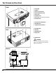
Part Names and Functions Front w q q Focus Ring w Speaker e Power Cord Connector r Infrared Remote Receiver t Zoom Lever y Projection Lens u Lens Cover (See page 48 for attaching.) i Air Intake Vent o Top Controls and Indicators !0 Air Intake Vent !1 Terminals and Connectors e Back r t y o !6 u !0 i !2 Air Intake Vent !3 Air Filter !4 Adjustable Feet !1 !5 Lamp Cover !6 Exhaust Vent CAUTION Hot air is exhausted from the exhaust vent. Do not put heat-sensitive objects near this side.
Part Names and Functions q w RGB IN-1/ COMPONENT IN e R * r AUDIO IN L SERVICE PORT t Part Names and Functions Terminal y VIDEO IN S-VIDEO IN COMPUTER AUDIO IN RESET AUDIO OUT RGB IN-2/ RGB OUT u q RGB IN-1/ COMPONENT IN Connect output signal from a computer (Analog RGB) or video equipment (Component or RGB Scart) to this terminal. Optional cables are required when using this terminal as component input or RGB Scart 21-Pin Video input. (p17.
Part Names and Functions Top Control q w e r MENU LV-X4 KEY STONE SET VOL - POWER VOL + LAMP REPLACE WARNING INPUT t y i q MENU button Opens or closes the On-Screen Menu. (p22) t INPUT button Selects input source. (p26, 34, 35 ) w SET button Executes the item selected. It is also used to expand / compress the image in Digital zoom +/– mode. (p33) y e KEYSTONE button Corrects keystone distortion.
Part Names and Functions q L-CLICK button Part Names and Functions Remote Control Unit Acts as left click for wireless mouse operation. (p12) w SIGNAL EMISSION indicator This indicator lights red while a signal is being sent from the remote control unit to the projector. e KEYSTONE button Corrects keystone distortion. (p24, 41) q r AUTO PC button Operates the Auto PC adjustment function. (p28) t COMPUTER button Selects input source (COMPUTER 1 or COMPUTER 2).
Part Names and Functions Pointer Function You can move Spotlight or Pointer of the projector with the remote control unit to emphasize a part of the projected image. ✔Note: You can choose the size of Spotlight (Large, Middle, and Small) and the pattern of Pointer (Arrow, Finger, and Dot) in the Setting Menu. See “Pointer” on page 44. 1 Press the POINTER button on the remote control unit to display the Spotlight or Pointer (Arrow, Finger or Dot) you have selected.
Part Names and Functions Part Names and Functions Remote Control Code This projector has eight different remote control codes (Code 1-Code 8); the factory-set, initial code (Code 1) and the other seven codes (Code 2 to Code 8). This switching function prevents remote control interference when operating several projectors or video equipment at the same time. (Change the remote control code for the projector first before changing that for the remote control unit. See “Remote control” on page 44.
Part Names and Functions Remote Control Battery Installation 1 Remove the battery compartment lid. Press the lid downward and slide it. 2 Slide the batteries into the compartment. 3 Replace the compartment lid. Two AA size batteries For correct polarity (+ and –), be sure battery terminals are in contact with pins in compartment. To insure safe operation, please observe the following precautions : ● Use (2) AA, UM3 or R06 type alkaline batteries. ● Replace two batteries at the same time.
Installation Positioning the Projector This projector is designed to project on a flat projection surface and can be focused from 3.3’(1.0m) - 25.3’(7.7m). Refer to the figure and the table below for the screen size and the distance between the projector and the screen. A:B = 9:1 25.3’ (7,7m) 16,1’ (4,9m) 12.5’ (3.8m) Max. Zoom 190” 190” 8,2’ (2,5m) 150” 3.3’ (1.0m) 40” A Min.
Installation Connecting the AC Power Cord This projector uses nominal input voltages of 100-120 V or 200-240 V AC. This projector automatically selects the correct input voltage. It is designed to work with single-phase power systems having a grounded neutral conductor. To reduce risk of electrical shock, do not plug into any other type of power system. Consult your authorized dealer or service station if you are not sure of the type of power being supplied.
Installation Connecting to a Computer Cables used for connection • VGA Cable (HDB 15 pin) (Only a cable is supplied.) • USB Cable • Audio Cables (Mini Plug: stereo) ✽ (✽ = Not supplied with this projector.
Installation Connecting to Video Equipment Cables used for connection • Video and Audio Cable (RCA x 3) ✽ • S-VIDEO Cable ✽ • Audio Cables (Mini Plug: stereo) ✽ (✽ = Not supplied with this projector.
Installation Connecting to Component Video Equipment Cables used for connection • Audio Cables (Mini Plug (stereo) x 2 or RCA x 2) ✽ • Scart-VGA Cable ✽ • Component-VGA Cable ✽ (Separately supplied as LV-CA32) (✽ = Not supplied with this projector.
Basic Operation Turning On the Projector 1 Complete peripheral connections (with a computer, VCR, etc.) before turning on the projector. 2 Connect the projector's AC power cord into an AC outlet. The POWER indicator blinks red in a moment and lights red. 3 Press the POWER button on the top control or on the remote control unit. The POWER indicator turns green lighting and the cooling fans start to operate. The preparation display appears on the screen and the count down starts.
Basic Operation Turning Off the Projector 1 Press the POWER button on the top control or on the remote control unit, and a message "Power off?" appears on the screen. 2 Press the POWER button again to turn off the projector. The POWER indicator starts to blink red, and it continues while the cooling fans are operating for about 90 seconds. (About 120 seconds when the fan mode is L2. See page 46.) The message disappears after 4 seconds.
Basic Operation How to Operate the On-Screen Menu The projector can be adjusted or set via the On-Screen Menu. Refer to the following pages regarding each adjustment and setting procedure. On-Screen Menu Menu icon 1 Press the MENU button to display the On-Screen Menu. 2 Press the Point 7 8 button to select a Menu icon to adjust. Press the Point ed button to select an item to adjust. Pointer (red frame) Press the Point d button to move the pointer. 3 Press the SET button to show the item data.
Basic Operation Menu Bar For computer source Guide Window PC System Menu Image Select Menu Screen Menu Setting Menu Shows the selected Menu of the OnScreen Menu. Used to select computer system. (p27) Used to select an image level among Standard, High contrast,Blackboard (Green), and Custom.(p31) Used to adjust size of image. [Normal / True / Wide / Digital zoom +/–] (p33) Used to change settings of the projector or reset lamp replace counter.
Basic Operation Zoom and Focus Adjustment Rotate the Zoom Lever to zoom in and out. Rotate the Focus Ring to adjust the projected picture focus. Zoom Lever Focus Ring Keystone Adjustment If a projected picture has keystone distortion, correct the image with KEYSTONE adjustment. 1 Press the KEYSTONE button on the top control, the remote control unit or select Keystone in the Setting Menu (p41). The keystone dialog box appears. 2 Correct keystone distortion by pressing the Point ed button.
Basic Operation No Show Function Press the NO SHOW button on the remote control unit to black out the image. To restore to normal, press the NO SHOW button again or press any other button. When a projected image is captured and set as “User” in the Logo item in the Setting Menu (p42), the screen changes each time you press the NO SHOW button as follows. black out ➜ the captured image ➜ normal ➜ • • • • • The message disappears after 4 seconds.
Computer Input Input Source Selection Direct Operation Choose either Computer 1 or Computer 2 by pressing the INPUT button on the top control or press the COMPUTER button on the remote control unit. Before using these buttons, correct input source should be selected through menu operation as described below. INPUT button Computer 1 Computer 2 ✳ Video COMPUTER button Computer 1 Computer 2 ✳ ✳ See Note on the bottom of this page.
Computer Input Computer System Selection This projector automatically tunes to various types of computers based on VGA, SVGA, XGA or SXGA with its Multi-scan system and Auto PC Adjustment. If Computer is selected as a signal source, this projector automatically detects the signal format and tunes to project a proper image without any additional setting. (Signal formats provided in this projector is shown on page 57 ) ✔Note: The projector may display one of the following messages.
Computer Input Auto PC Adjustment Auto PC Adjustment function is provided to automatically adjust Fine sync, Total dots, Horizontal, and Vertical to conform to your computer. Auto PC Adjustment function can be operated as follows. Auto PC Adj. 1 Press the MENU button to display the On-Screen Menu. Press the Point 7 8 button to move the red frame pointer to PC Adjust Menu icon. 2 Press the Point d button to move the red frame pointer to Auto PC Adj. icon and then press the SET button twice.
Computer Input Manual PC Adjustment Some computers employ special signal formats which may not be tuned by Multi-scan system of this projector. Manual PC Adjustment enables you to precisely adjust several parameters to match those signal formats. The projector has 5 independent memory areas to memorize those parameters manually adjusted. It allows you to recall the setting for a specific computer. PC Adjust Menu icon 1 Press the MENU button and the On-Screen Menu will appear.
Computer Input Display area Select the resolution at the Display area dialog box. Press the SET button at the Display area icon and the Display area dialog box appears. Display area H Adjusts the horizontal area displayed by this projector. Press the Point 7 8 button to decrease/increase value and then press the SET button. Display area Display area V Adjusts the vertical area displayed by this projector. Press the Point 7 8 button to decrease/increase value and then press the SET button.
Computer Input Image Level Selection Direct Operation Select an image level among Standard, High contrast, Blackboard(Green), Custom by pressing the IMAGE button on the remote control unit. IMAGE button Standard High contrast Standard Normal picture level preset on this projector. Blackboard(Green) High contrast Picture adjustment improved in reproduction of the halftones. This adjustment is suitable for providing a better image in a brighter place.
Computer Input Image Level Adjustment 1 Press the MENU button and the On-Screen Menu will appear. Press the Point 7 8 button to move the red frame pointer to the Image Adjust Menu icon. 2 Press the Point d button to move the red frame pointer to the item that you want to adjust, and then press the SET button. The level of each item is displayed. Adjust each level by pressing the Point 7 8 button.
Computer Input Screen Size Adjustment This projector has a picture screen resize function, which enables you to display the desirable image size. 1 Press the MENU button and the On-Screen Menu will appear. Press the Point 7 8 button to move the red frame pointer to the Screen Menu icon. 2 Press the Point d button and move the red frame pointer to the function that you want to select and then press the SET button.
Video Input Input Source Selection (Video, S-Video) INPUT button Direct Operation Video Choose Video by pressing the INPUT button on the top control or the VIDEO button on the remote control unit. Before using these buttons, correct input source should be selected through menu operation as described below. Computer 1 Computer 2 ✳ VIDEO button Video ✳ See Note on the bottom of this page. Input Menu icon Menu Operation 1 Press the MENU button and the On-Screen Menu will appear.
Video Input Input Source Selection (Component, RGB Scart 21-Pin) Direct Operation INPUT button Computer 1 Choose Computer 1 by pressing the INPUT button on the top control or press the COMPUTER button on the remote control unit. Before using these buttons, correct input source should be selected through menu operation as described below. Computer 2 ✳ Video COMPUTER button Computer 1 Computer 2 ✳ ✳ See Note on the bottom of this page.
Video Input Video System Selection 1 Press the MENU button and the On-Screen Menu will appear. Press the Point 7 8 button to move the red frame pointer to the AV System Menu icon. 2 Press the Point d button to move the red arrow pointer to the system that you want to select and then press the SET button. Video or S-Video Auto The projector automatically detects incoming video system, and adjusts itself to optimize its performance. When Video System is PAL-M or PAL-N, select system manually.
Video Input Image Level Selection Direct Operation IMAGE button Standard Select a desired image level among Standard, Cinema, Blackboard (Green), Custom by pressing the IMAGE button on the remote control unit. Standard Normal picture level preset on this projector. Cinema Blackboard(Green) Custom Cinema Picture level adjusted for the picture with fine tone. Blackboard(Green) Picture level suitable for the image projected on a blackboard. This mode assists to enhance the image projected on a blackboard.
Video Input Image Level Adjustment 1 Press the MENU button and the On-Screen Menu will appear. Press the Point 7 8 button to move the red frame pointer to the Image Adjust Menu icon. 2 Press the Point d button to move the red frame pointer to the item that you want to adjust and then press the SET button. The level of each item is displayed. Adjust each level by pressing the Point 7 8 button.
Video Input Progressive Interlaced video signal can be displayed in a progressive picture. Off . . . .Not activated. L1 . . . . .Select “L1” for an active picture. L2 . . . . .Select “L2” for a still picture. “OK?” message Move the pointer to [Yes] and then press the SET button. Film This function is effective on 3:2 pulldown video source. With this function On, the projector reproduces pictures faithful to the original film quality. Reset Resets all adjustment to their previous figure.
Video Input Screen Size Adjustment This projector has a picture screen resize function, which enables you to display the desirable image size. 1 Press the MENU button and the On-Screen Menu will appear. Press the Point 7 8 button to move the red frame pointer to the Screen Menu icon. 2 Press the Point d button and move the red frame pointer to the function that you want to select and then press the SET button. Normal Provides image at a normal video aspect ratio of 4 : 3.
Setting Setting This projector has Setting menu that allows you to set up the other various functions described as follows; Press the MENU button to display the On-Screen Menu. Press the Point 7 8 button to move the red frame pointer to the Setting Menu icon. 2 Press the Point d button to move the red frame pointer to the item that you want to set and then press the SET button. The Setting dialog box appears. Set the red frame pointer to the item and press the SET button.
Setting Enter a Logo PIN code Select a number by pressing the Point 7 8 button and fix the number with the SET button. The number will change to "✳". If you fixed a wrong number, move the pointer to "Set" or "Clear" once by pressing the Point d button, then return to "Logo PIN code". Enter the correct number again. Repeat this step to complete entering a four-digit number. When the four-digit number is fixed, the pointer will automatically move to "Set".
Setting Ceiling Ceiling Setting When this function is “On,” the picture is top/bottom and left/right reversed. This function is used to project the image from a ceiling mounting the projector. Rear When this function is “On,” the picture is left/right reversed. This function is used to project the image to a rear projection screen. Rear Terminal The RGB IN-2/RGB OUT terminal on the back of the projector is switchable for computer input or monitor output.
Setting Lamp mode This function allows you to change brightness of the screen. Normal mode ···· normal brightness Auto mode ···· the controlled brightness according with input signal Silent mode ···· lower brightness reduces the lamp power consumption and extends the lamp life. The sound is quiet. ✔Note: Lamp mode is not switched into Silent mode within 2 minutes after the projector is turned on. Pointer Pointer You can emphasize a part of the projected image with this function.
Setting Key lock Key lock Select Key lock and this box appears. Choose one of these with the Point ed button and select [Yes] to activate it. If the top control accidentally becomes locked and you do not have the remote control unit nearby, disconnect the AC power cord from the AC outlet, and then while pressing the SET button, reinsert the AC power cord. This will release the top control lock. PIN code lock Setting This function locks operation of the top control and remote control unit.
Setting To Change the PIN code lock setting Select Off, On1, or On2 with the Point 7 8 button and then "Quit" with the Point d button and press the SET button to close the dialog box. To Change the PIN code The PIN code can be changed to your desired four-digit number. Select "PIN code change" with the Point d button, and press the SET button. The New PIN code input dialog box will appear. Change the PIN code lock setting Select a desired setting with the Point 7 8 button.
Maintenance and Cleaning Warning Indicator The WARNING indicator shows the state of the function which protects the projector. Check the state of the WARNING indicator and the POWER indicator to take proper maintenance. The projector is shut down and the WARNING indicator is blinking red.
Maintenance and Cleaning Cleaning the Air Filters Air filters prevent dust from accumulating on the surface of the optical elements inside the projector. Should the air filters become clogged with dust particles, it will reduce cooling fans’ effectiveness and may result in internal heat build up and adversely affect the life of the projector. Clean the air filters following the steps below. 1 Turn off the projector, and disconnect the AC power cord from the AC outlet.
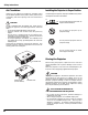
Maintenance and Cleaning Cleaning the Projection Lens Follow these steps to clean the projection lens. Disconnect the AC power cord before cleaning. 2 Softly wipe the projection lens with a cleaning cloth that contains a small amount of non-abrasive camera lens cleaner, or use lens cleaning paper or a commercially available air blower to clean the lens. Avoid using an excessive amount of cleaner. Abrasive cleaners, solvents, or other harsh chemicals might scratch the surface.
Maintenance and Cleaning Lamp Replacement When the life of the projection lamp of this projector draws to an end, the LAMP REPLACE indicator lights yellow. If this indicator lights yellow, replace the lamp with a new one promptly. Top Control This indicator lights yellow when the life of the projection lamp draws to an end. CAUTION KEY STONE VOL + LAMP REPLACE CAUTION Allow a projector to cool, for at least 45 minutes before you open the Lamp cover. The inside of the projector can become very hot.
Maintenance and Cleaning Lamp Replace Counter Be sure to reset the lamp replace counter after the lamp is replaced. When the lamp replace counter is reset, the LAMP REPLACE indicator stops lighting. Turn the projector on, press the MENU button and the OnScreen Menu will appear. Press the Point 7 8 button to move the red frame pointer to the Setting Menu icon. 2 Press the Point d button to move the red frame pointer to the Lamp counter reset item and then press the SET button.
Appendix Troubleshooting Before calling your dealer or service center for assistance, check the items below once again. – Make sure you have properly connected the projector to peripheral equipment as described in "Connecting to a Computer" and “Connecting to Video Equipment” on page17-19. – Make sure all equipment is connected to AC outlet and the power is turned on. – If the projector does not project an image being operated with a computer, restart the computer.
Appendix Some displays are not seen during the Operation. – Check the Display item. (See “Setting” on page 41.) PIN code dialog box appears at start-up. – PIN code lock is being set. Input a PIN code (1234 or numbers you have set). (See “PIN code lock” on page 20,45 and 46.) Computer 2 cannot be selected. – Select Computer 2 at the Terminal item in the Setting Menu. (See “Setting” on page 43.) The Terminal item cannot be selected.
Appendix Indicators and Projector Condition Check the indicators to see the projector condition. Indicators POWER WARNING LAMP REPLACE red/green red yellow Projector Condition The projector is OFF. (The AC power cord is unplugged.) • • • lights green. ✽ When ✽ The projector is preparing for stand-by or the projection lamp is being cooled down. The projector cannot be turned on until cooling is completed. ✽ The projector is ready to be turned on with the POWER button.
Appendix Menu Tree Computer Input / Video Input Input RGB Go to System (1) Component Go to System (2) RGB( Scart ) N/A Computer 2 RGB Go to System (1) Video Auto Go to System (3) Video Go to System (3) S-Video Go to System (3) Computer 1 ✽N/A - - - not applicable Sound Sound Volume Mute Quit 0 - 63 On / Off Computer Input System (1) Standard High contrast Blackboard(Green) Custom Image Adjust 0 - 31 Contrast Brightness Color Temp 0 - 63 0 - 63 High Mid Low XLow 640 x 480 720 x 40
Appendix Setting Video Input System (2) Auto 1080i 1035i 720p 575p 480p 575i 480i System (3) Auto PAL SECAM NTSC NTSC 4.
Appendix Compatible Computer Specifications Basically this projector can accept the signal from all computers with the V, H-Frequency below mentioned and less than 130 MHz of Dot Clock.
Appendix Technical Specifications Mechanical Information Projector Type Dimensions (W x H x D) Net Weight Feet Adjustment Multi-media Projector 11.81" x 3.69" x 9.40" (300mm x93.8mm x 238.8mm) (Not including adjustable feet) 6.4lbs (2.9kgs) 0˚ to 11.9˚ Panel Resolution LCD Panel System Panel Resolution Number of Pixels 0.
Appendix Accessories Owner's Manual AC Power Cord Remote Control Unit and Batteries VGA Cable USB Cable Lens Cover with String and Screw Soft Carrying Bag PIN code Label ● The specifications are subject to change without notice. ● LCD panels are manufactured to the highest possible standards. Even though 99.99% of the pixels are effective, a tiny fraction of the pixels (0.01% or less) may be ineffective by the characteristics of the LCD panels.
Appendix Configurations of Terminals RGB INPUT/COMPONENT INPUT/RGB OUTPUT TERMINAL (ANALOG) Terminal : HDB15-PIN Pin Configuration 4 5 10 15 14 2 3 9 8 13 1 7 12 1 2 3 4 5 6 7 8 6 11 Red (R/Cr) Input / Output Green (G/Y) Input / Output Blue (B/Cb) Input / Output ----Ground (Horiz.sync.) Ground (Red) Ground (Green) Ground (Blue) 9 10 11 12 13 14 15 ----Ground (Vert.sync.) Ground / --------Horiz. sync. Input / Output (Composite H/V sync.) Vert. sync.
Appendix While the projector is locked with the PIN code... Put a label below on in a prominent place of the projector's body while it is locked with a PIN code. The label is provided with the product to identify the projector locked with a PIN code.
CANON INC. 30-2, Shimomaruko 3-chome, Ohta-ku, Tokyo 146-8501, Japan CANON U.S.A., INC. One Canon Plaza, Lake Success, NY 11042-1198, U.S.A. CANON CANADA, INC. 6390 Dixie Road Mississauga, Ontario L5T 1P7 Canada CANON LATIN AMERICA, INC. 703 Waterford Way Suite 400 Miami, Florida 33126 U.S.A. CANON EUROPA N.V. P.O.Box 2262, 1180 EG Amstelveen, The Netherlands CANON COMMUNICATION & IMAGE FRANCE S.A. 102, Avenue du General de Gaulle, 92250 La Garenne Colombes, France CANON (UK) LTD.