
User`s manual


T460/461/T462 Manual 26th Sept 2008. V2.79 Part B © JED Microprocessors Pty Ltd
10
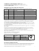
Switched source option
The EMP-7200 (and probably some of the others in this series) has a “source” switching switch on the connector panel. This
selects the source of the second PC channel.
In the UP position, the two PC positions are the COMPUTER1 and COMPUTER2 D15 connectors on the connector panel.
One video channel is allowed and this auto-switches between normal video and S-video, depending on which connector is
active. No remote video switching is allowed.
If this is the desired setup, setup the channel selection in the T460 to use Channels 1 and 2 as PC1 and PC2, channel 3 as video
(choose video or S-video labels), and skip channel 4.
In the DOWN position, COMPUTER1 is the only D15 channel available and this should be called PC1. Skip channel 2, use
channel 3 as Video or S-video, and channel 4 is now BNC connector inputs which can be labelled as desired (eg Computer 2).
In any fixed setup, only three channels are ever available. By using 4 channels in this way and setting either 2 or 4 as skipped
channels, the same software can be used for both switch positions.
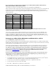
Epson level 5 projectors: EMP/ELP 50/51/70/72/500/503/700/703/710/713/5350/7250/7350,
EMP 8000/9000
This family of projectors all uses the same protocol. Communications runs at 9600 8N1.
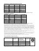
T460 Channel Code, 6
th
byte Connector
Channel 1 010h PC1
Channel 2 011h PC2 (some only)
Channel 3 021h Video (RCA)
Channel 4 022h S-Video
Channel 5 030h BNC-RGB (some only)
Channel 6 040h BNC-YCbCr (some only)
Don’t forget to set all unused T460 channels to “Skip” to jump over blank/unused inputs in all the above tables.
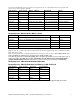
Connections (except EMP 8000/9000) ***Note: Some may need wiring as 7250/8000/9000
The serial connection is made via a special “Y” cable, called in the projector user’s manual the “main” cable. This plugs into
the “Mouse/COM 1” connector and splits into a “serial” cable and a “mouse” cable.
In the setup with a T460 controller, the “serial” end of the “Y” cable is used with a male D9 connector that is wired to the
4-pin Projector (J6) connector on the T460.
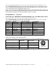
On some, there is a 9-pin Mini DIN … connections are also shown for these:
Function Projector (J6) connector
on T460
D9 connector to
“main” cable
Mini DIN 9-pin
Ground Pin 1 Pin 5 Pin 9
Serial TX out to projector Pin 2 Pin 3 Pin 5
Serial RX into T460 from proj. Pin 3 Pin 2 Pin 4
DTR out to projector Pin 4 Pin 7 Pin 6 ***
CTS out to projector Pin 4 Pin 4 Pin 4 ***
After installation wiring of any projector to a T460, use a multimeter to check voltages of –9 on BOTH TX and RX pins in any
installation, as described in the troubleshooting part of this manual. See following note re setup of #1 >< #2 position
*** Pin 6 DTR, pin 7 DSR and pin 8 IDO are not defined in data to date. We are trying to pin that down with Epson.