
Specifications


CHAPTER 4 IMAGE FORMATION SYSTEM
COPYRIGHT
©
1999 CANON INC. CANON NP6512/6612/7120/7130/7130F REV.0 AUG. 1999 PRINTED IN JAPAN (IMPRIME AU JAPON)
4-9
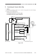
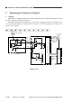
D. Controlling the Transfer Roller Bias
1. Outline
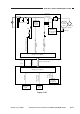
The circuit shown in Figure 4-105 is used to control the voltage applied to the transfer charging
roller, and has the following functions:
• Turning on and off the transfer bias.
• Controlling the transfer bias to a constant voltage.
• Correcting the transfer bias voltage level (ATVC)
• Switching the transfer bias polarity (cleaning bias)
Figure 4-105
Main
transformer
Transfer positive DC
bias generation circuit
Transfer positive DC bias ON signal
T_REV_ON*
T101
Transfer current detection signal
T_FW_S
Photo-
sensitive
drum
Transfer
charging
roller
Transfer DC bias
control signal
T_FW_DRV
Transfer bias voltage
detection signal
T_FEEDBACK
Transfer DC bias ON signal
T_FW_ON
High-voltage transformer
control signal
CLK32K
Transfer overcurrent detection signal
HV_LIMIT
+24V
T302
Transfer
high-voltage
transformer
Serial
communi-
cation
(Q101) (Q900)
Microprocessor
Microprocessor
DC controller PCB Composite power supply PCB
Transfer bias
detection circuit
Transfer bias
control circuit