
Specifications


CHAPTER 7 EXTERNALS/AUXILIARY MECHANISMS
COPYRIGHT
©
1999 CANON INC. CANON NP6512/6612/7120/7130/7130F REV.0 AUG. 1999 PRINTED IN JAPAN (IMPRIME AU JAPON)
7-4
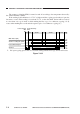
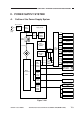
B. Power Supply Circuit
The machine's power supply consists of a composite power supply circuit in which a DC power
supply, scanning lamp power supply, and high-voltage power supply are integrated on a single
board. It also possesses a microprocessor for exchanges of various data with the machine's DC
controller PCB.
The machine's power switch is a soft switch, and the machine is equipped with an auxiliary
power supply used to operate the switch. The auxiliary power supply provides the microprocessor
(Q900) with +5 V as long as the door switch (DS1) remains on.
AC power is supplied to the DC power supply when the power switch on the control panel is
turned on. In response, the DC power supply provides the DC controller PCB with +5 V, +24 VR,
and +24 VU.
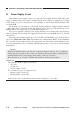
When the power switch is turned off, power to the DC controller PCB is cut; to back up data on
error codes (E000, E001, E002, E003), the machine uses a litium battery (BAT1) located within the
DC controller circuit; using the battery, the appropriate error information will be indicated on the
control panel when the power is returned, informing the presence of an error associated with the
fixing heater.
Reference:
The tolerances in DC voltage are as follows:
• +5 V ±5%
• +24 VR ±5%
• +24 VU -10.0%, +12.5%
For +24 VR, two types of voltage are used:
• During copying, +24 V ±5%
• During standby, +18 V ±10%
However, the above assume that the deviations in AC input are -15%, +10%.
Caution:
Replace the lithium battery only with the one listed in the Parts Catalog. Use of a different
battery may present a risk of fire or explosion. The battery may present a fire or chemical burn
hazard if mistreated. Do not recharge, disassemble, or dispose of it in fire.
Keep the battery out of reach of children and discard any used battery promptly.