
Specifications


11-3
COPYRIGHT
©
1999 CANON INC. CANON NP6512/6612/7120/7130/7130F REV.0 AUG. 1999 PRINTED IN JAPAN (IMPRIME AU JAPON)
I. MAINTENANCE AND INSPECTION
A. Image Adjustment Basic Procedure
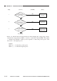
Making Pre-Checks Adjusting the Optimum Density
Clean the parts.
Is the copy density
correction dial (VR107)
centered?
Set it at
the center.
Select non-AE, and set the copy density
adjusting lever to the middle index; then,
make two to three copies of the Test
Sheet (NA-3).
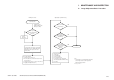
Check the following:
1. Density of gray scale No. 9
2. Presence/absence of difference between front
and rear (Note 1)
3. Density of gray scale No. 1 (good or bad; Note 1)
4. Fogging of background (Note 1)
NO
YES
Scanning system,
pickup/feeding system,
delivery assembly
Check the following:
1. Drum unit
2. Scanning lamp
3. AE sensor PCB
4. DC controller PCB
5. Composite power supply PCB
(See the appropriate troubleshooting
procedure.)
Is the optimum
density obtained by intensity
adjustment?
(Note 2)
Can the
deviation be corrected
using the copy density correction
dial (VR107)?
Is gray scale No. 9
barely visible?
END
YES
YES
YES
NO
NO
NO
Note:
1. The machine is not equipped with a function to
correct image faults. See the appropriate
troubleshooting procedure.
2. See p. 11-42.