
Specifications

CHAPTER 11 TROUBLESHOOTING
COPYRIGHT
©
1999 CANON INC. CANON NP6512/6612/7120/7130/7130F REV.0 AUG. 1999 PRINTED IN JAPAN (IMPRIME AU JAPON)
11-67
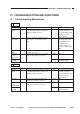
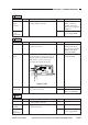
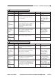
6 E064
YES/NO
YES
NO
YES
YES
YES
YES
NO
Cause
Wiring
High-voltage
contact
Transfer
charging
roller
Primary
charging
roller
High-voltage
cable
Composite
power
supply PCB
DC control-
ler PCB
Step
1
2
3
4
5
6
Checks
Turn off and then on the power switch;
then, set the copy count to '1'. Is 'E064'
indicated at the end of a copying run?
Is the connection between the high-
voltage contacts of the machine's top
and bottom units normal?
Is the transfer charging roller or the
contact faulty?
Replace the drum unit. Is the problem
corrected?
Does the high-voltage cable have
scratches or tears?
Replace the composite power supply
PCB. Is the problem corrected?
Action
Check the wiring
between the DC
controller PCB and the
composite power
supply PCB. Check
the wiring between the
composite power
supply PCB and the
high-voltage contact
PCB.
Correct the high-
voltage contacts of the
machine's top and
bottom units.
Replace the transfer
charging roller.
End.
Replace the high-
voltage cable.
End.
Replace the DC
controller PCB.
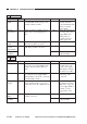
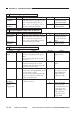
5 E030
YES/NO
NO
YES
NO
Cause
Wiring
Total copy
counter
DC control-
ler PCB
Step
1
2
Checks
Is the wiring from the total counter to
the connector J119 on the DC control-
ler PCB normal?
Replace the total copy counter. Is the
problem corrected?
Action
Correct the wiring.
End.
Replace the DC
controller PCB.