
Specifications

CHAPTER 3 EXPOSURE SYSTEM
COPYRIGHT
©
1999 CANON INC. CANON NP6512/6612/7120/7130/7130F REV.0 AUG. 1999 PRINTED IN JAPAN (IMPRIME AU JAPON)
3-18
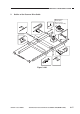
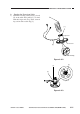
Figure 3-307
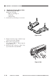
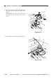
Figure 3-308
[1]
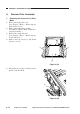
3. Routing the Scanner Drive Cable
a. Before Starting the Work
Prepare the following:
• Mirror positioning tool
• Cable clip
• Adhesive tape
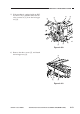
1) Set the mirror positioning tool as shown.
2) Prepare about five strips of adhesive tape
(each one about 20 × 50 mm).
3) Remove the copyboard glass.
(See Chapter 7.III.C.1. “Removing the
Copyboard Glass.”)
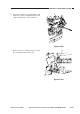
4) Disconnect the connectors (J101, J131)
[1] from the DC controller PCB.