2000 Fire Door-Fan Manual Single Blower Panel Set Up Large room testing with 2 Blowers Range Selection with Model N digital console OR, Model L digital control panel OR, Model E analog gauge clip Or, E43 Aluminum Frame Set Up Leak check at + 15Pa Room pressure Smoke test & measure static pressure Room and Flow Pressure Readings Windy test conditions Mixing or NO mixing? 2000 Fire Door-Fan Manual updated 2002-05-28 Page 1 of 58
What to do if room fails.
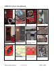
Single Blower Panel Set Up Select a doorway where the air will be blown into the largest space so the air can find its way back to the leak. Set the panel bag close to the door. Open panel bag and remove the Blower Panel with the 22-inch hole in it. Open Blower Panel and position back edge against the doorstop. Pull top strap tight and secure strap in the nylon cleat. Press the loop against the Velcro to keep strap ends neat.
Cinch lower strap tight and secure strap in cleat. The small fill-in sheet is positioned first in the groove. It fills in the gap for doors up to 36” Smooth down the fill-in sheet from top to bottom Place the large X-Panel in the top of the doorway. Cinch and lock the pull strap to secure the panel. Place blower case next to the doorway.
Hook the bottom foot on the blower through the hole in the center of the panel. Align the nylon block on top of the blower with the panel cutout, insert and rotate the blower till the top is horizontal to lock it into the panel. The blower is mounted in the Flow Away position. This is always first. When the test is complete in this direction, the blower is removed and installed with the Flow Towards the operator. Blower is upright and locked in place.
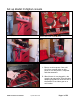
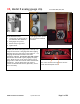
Set up Model N digital console Place Laptop Console on blower case. Remove the control cords Set rocker switches OFF by pressing the “0” so blowers don’t come on accidentally. Place the cords next to the panel set. Power to console comes from: 1. Blower receives power from wall. Cord from console picks up this power to run the printer, computer and thermometers. 2.
Your laptop computer power supply plugs into the female plug inside the console. The power supply cord is then led through this hole to the computer above.
OR, Model L digital control panel for Models L64 and L63 The control panel can sit on top of the blower case with your laptop beside it.
OR, Model E analog gauge clip The Gauge Clip attaches to the door or the Aluminium frame. 1. Loosen knob on gauge plate to accommodate door thickness. 2. Hold gauges at eye level. 3. Rotate clamp to grip door. 4. Tighten knob. Gauges mounted on door. Top 60-gauge slides up and off to be used as handheld as needed. Zero gauges by blowing in the tubes and capping them off with your thumb so the gauge stays at the top of its range for 30 seconds.
OR, DM-1 digital gauge for models J64 The digital gauge can be hand held and used to measure static pressure, room pressure and flow pressure. Connect a tube from the panel to the right hand port of the DM-1 to get room pressure. Then connect a tube from the DM-1 to the blower to get flow pressure.
Take the 7ft red tube and throw outside, away from the air blast of the door fan and if outdoors, away from wind if possible. If you were testing from outside the room, this tube would then get thrown inside. Insert the motor control connector into the receptacle till it clicks. E and J models will not have a control connector since the knob on the blower is used. Plug the clear flow pressure pick-up tube into the nylon quick-connect on top of the blower. Gently push while giving it a quarter turn.
Install the X-Y Panel. Expand the X-Y panel horizontally by hand. Expand the X-Y Panel vertically with the center strap. Cinch and lock the vertical strap in the cleat. Tighten and lock the horizontal straps in their cleats. Ensure rocker switches are OFF at the control panel. Plug power cord into wall outlet then into blower. Set rocker switch on blower to “remote” so it can be controlled by the console or control panel.
Red tube is always extended away from the air-stream on the opposite side of the door.
This detailed picture shows white dots that should line up. Later models may have molded dots. This vertical bar should line up on each sheet.
Large room testing with 2 Blowers Models N64 and L64 Use the second blower panel. Install it above the lower blower panel. Install the second blower in the upper panel. For added security: 1. mount the panels on the far side of the doorstop so the weight of the blowers pulls them into the stop 2. apply 2-inch clear tape to both sides of the upper panel where it contacts the doorframe Use second cord set from console to control the speed of blower #2.
Or, E43 Aluminum Frame Set Up Open case Take out pieces Assemble flat. Line up numbers. Connect corners Fit frame loosely into doorway. Adjust knobs to hold the size Cover with cloth Fit frame and cloth into door way.
Actuate cam levers Frame is installed. Use Velcro to hold blower Finished installation. This install will take about 20 minutes the first time. It will take less time with practice. The main advantage of the Aluminum frame is slightly smaller package for shipment and lower cost. 2000 Fire Door-Fan Manual updated 2002-05-28 Hook elastic under blower.
Leak Check The Purpose of the leak check is to locate the major leaks in the enclosure before performing the door fan test. Often large holes are located that must then be sealed before the door fan test can begin. Sometimes the smoke test identifies dampers that are not closing correctly or not at all. If so, that damper must be repaired before the test can proceed. Leak check.
Smoke test & measure static pressure The purpose of this test is to see whether there is a static pressure in the room prior to the door fan test. The door fan is not running and smoke is puffed in front of an open hole in the blower. If it moves slowly or not at all, no pressure exists. Minor pressures are cancelled out by testing both directions so we are therefore looking for significant movement of 2 mph (3kph).
Select Blower Range Principles of Infiltrometer Air Flow Measurement The Infiltrometer can accurately measure airflow between 18 CFM and 6500 CFM. However, in order to measure accurately over this wide range, the range must be changed as described in the following section. The Infiltrometer fan blade pushes air out the back of the fan creating a negative pressure in front of the blades. This negative pressure pulls air through the fan's rounded (venturi) shaped inlet. More negative pressure, more flow.
Range Selection Procedure Always start with the restrictor plate off - that's called Range 22 for the 22" diameter inlet. Give the speed control a quick half turn to get the motor moving then QUICKLY turn the control DOWN if required. As you increase the fan speed, the Room Pressure gauge will rise. If the room is quite tight, it will rise very quickly. (Never let the Room Pressure rise above 60 Pa.
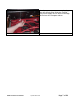
Flow Range Diagram Always start in the Flow Away position. Adjust speed till room pressure is reached. Fan must be running at least at half speed and flow pressure must be greater than room pressure. If not, insert the Range A plate and keep changing to lower ranges till motor is at least half speed and flow pressure must be greater than room pressure.
Range C1 - Flow Away Range 22 - Flow Towards Range A - Flow Towards. The inlet is now on the other side. Look at “Flow Away” picture to see what the inlet must look like. Range B - Flow Towards. The inlet is now on the other side. Look at “Flow Away” picture to see what the inlet must look like. Range C8 - Flow Towards. The inlet is now on the other side. Look at “Flow Away” picture to see what the inlet must look like. Range C4 - Flow Towards. The inlet is now on the other side.
Room and Flow Pressure Readings Make sure the blower is running at half speed or more before taking any readings. Analog Gauge Readings ...from the Magnehelic gauges from the Model E Analog Gauge Clip Tubing Connections: For the 60-gauge- connect the red tube from the upper port through the panel. When the blower is reversed, the red tube must be connected to the lower port. For the 250-gauge, plug the clear tube from the lower gauge port into the blower. Gauge Reading Rules • Ensure the gauges are zeroed.
60 gauge readings Read the upper scale only. Reverse the tubes when you turn the fan around to test in the other direction. Taking Readings from Two Blowers If one blower can't get adequate Room Pressure, remove the upper panel cover and install a second blower. To be absolutely sure the upper panel will stay in place during the test, tape the edges of the upper panel to the door frame using clear box sealing tape or masking tape. Don't use duct tape.
Digital Gauge Readings Model DM-1 Digital Gauge for models N64, N63, L64, L63, J64, J63 1. Connect the 3 inch red tube from the Console or Digital Control Panel to the right port of the DM-1. Tips Re-Zero … prior to taking a new set of readings. Changes in temperature or position may affect the zero by 0.1 to 0.4 Pa but overall the drift will be minor. It is best not to re-zero before a test is completed. Take readings for both pressurize and depressurize without re-zeroing the DM-1.
1.Turn ON the DM-1. Wait 30 seconds. Set first toggle to “ZERO” 2. Press “Set to Zero” on DM-1 3. Set all toggles up. They should be in the “Test, Room & Flow #1” positions. 4. When this light is lit, all connections have been made at blower and it’s ready to go. Turn on the power to blower #1. 5. Adjust the speed control to get the required room pressure. The blower must run at half speed or more. If not change to a lower (more restrictive) range. Read the room pressure for 30 seconds. 6.
Two blowers for large rooms, (see also section on flex-duct testing) Use the second control cord for blower #2. Install while the blower is on the ground, and then install the blower in the panel. Complete steps 1 to 3 on the previous page first. Then go to step 7. 7. Turn on the power to blower #1 and #2. 8. Adjust the speed controls to get the required room pressure. Read the room pressure for 30 seconds. 9. When the desired room pressure is achieved, flip the toggle up to “Flow”.
Windy Conditions If the gauges fluctuate more than 1 Pa due to wind, follow these steps to reduce the fluctuations in the gauge reading. Tip: instead of taking readings at low room pressures around 10 Pa, perform the test at 60 Pa room pressure. The effect will be to reduce the retention time slightly but overall the test will be more accurate. Plug the red tube into the open end to the T on the 25' + 50' red wind damping tubes.
Use averaging on digital gauge to reduce the effect of wind. Set the Time averaging to 5 seconds. If the second reading varies more than 10% from the first reading, set it to 10 seconds. If the variation is still too much, set it to 30 seconds. Take at least three readings. The last two must be within 5% of each other in order for it to be useable.
Deluxe Wind Damping System to Stop Gauge Needles Moving If the room pressure gauge fluctuates more than 1 Pa due to the wind and the standard two tube damping system does not reduce them sufficiently then the optional wind damping system may be more effective. The time constant of the system is designed to decrease swings due to wind. If swings are due to other causes the wind damping system may not help.
Mixing or No Mixing (Descending Interface) or Extended Discharge Mixing means that as agent leaks out the incoming air is continually mixed with the remaining agent in the room so that the concentration is constant throughout. Mixing gives equal protection to all levels in the enclosure. Sometimes the air-handlers must remain running during the retention time to keep equipment cool. Other times mixing must be used because protection is required at high levels.
If the room fails Equipment calibration is often blamed for these failures but in over 12 years of 500 companies testing, it has never been a factor. It is usually that he room leaks too much. Airsealing looks simple but should be left to Weatherization contractors; NOT general contractors who may think they can do it but seldom can. Enclosures with excessive leaks Seal leaks at all elevations and retest. Grace FS 3000 Elastomeric coating is the best solution to the biggest leak.
This will only help if there is continual mixing during the retention period. handlers are shut off at discharge, more agent will give less retention time. If the air- Rooms with suspended ceilings will double the retention time usually when agent is discharge above the ceiling for mixing and no mixing cases. Extended discharges will increase retention time for the duration of the discharge. Eliminate Static pressure during retention In cases where this is large, reducing it can increase the time.
Flex duct installation for ceiling neutralization Position the flex-duct case under the ceiling tile in which it will be installed and open the case. There must be minimal obstructions to airflow above and around the ceiling tile selected. Insert the flex-duct into the T-bar ceiling framework. The square sheet goes in next. . Hook the cuff under the lower foot of the blower and over the nylon block on top of the blower flange. Secure the Velcro cinch strap on the flex-duct blower cuff.
A ceiling tile is removed to allow the flex duct to be mounted Note how the flex-duct mounts in one half the tile opening whilst the Retrotec blanking sheet that comes with the flex duct fills the rest of the space previously occupied by the ceiling tile. In the corner is a 2x2 ft. grille leading to the ceiling plenum. This grille should be sealed off to better allow the ceiling to be neutralized. The upper blower is measuring lower room leaks whilst the lower blower neutralizes leaks above the ceiling.
Lower leak tests using: Plastic-on-Ceiling procedure This procedure is much more time consuming than using the flex duct. It consists of measuring the Lower Leaks by covering the ceiling with plastic. This takes a lot of time but does give good results particularly in small rooms. A temporary solid barrier to leakage through a suspended ceiling can be used instead of the neutral pressure used in the B-2.6.2 "Flex Duct" test.
The principal deviation from the normal procedure is that the test can only be conducted in one direction, i.e. as a pressurization test. Depressurizing almost inevitably pulls down the plastic. In a room without a suspended ceiling, plastic could be used to seal off undampered ducts at ceiling level to better determine how much of the room leakage is below ceiling level.
Lower leak Estimates using: Leak audit Set the door fan to produce a 15 Pa positive pressure. Open the door panel up to witness smoke moving at “full speed”. Locate enclosure leaks, measure the open area. Test the leak with smoke in the area where the leak was measured. Mark down the % of full speed that each leak appears to be.
Field calibration check with calibration plate Place the second Blower Panel on top the first Blower Panel and expand into position. Insert the fill-in sheet in the Blower Panel. Place the X-Y Panel on top the Blower Panel. Tighten and lock the X-Y Panel straps. Panels installed with upper panel cover with calibration holes ready for performing the field calibration test. Fielded Calibration Plate opened.
The Field Calibration Check is a procedure which enables the AHJ to determine that the door fan to be used on a test is sufficiently accurate, and that the technician knows how to operate the equipment. It is also a useful training exercise for an inexperienced operator gaining familiarity with the equipment. The Infiltrometer is set up to measure the BACKGROUND leakage of a small room. Next, a hole of known size is opened up and the room is re-measured with the Infiltrometer.
Tall doorways Small X panel being installed. X- Panel will add 10 inches to the height of the panels. The small and large X-Panels can be positioned above this panel set to fill doorways over 10 ft.
Packing up and moving equipment Blower case fits on Ruaax cart. Panel case goes over top 2000 Fire Door-Fan Manual Accessory bag goes on top. Console is carried.
Case protects blower for day to day transport but when shipped by separate carrier such as UPS the case must be placed inside its original shipping box or the equivalent. Make sure the smoke puffers go into the special outside pockets they were designed for. If packed inside a computer case they may destroy the computer! Packing must be marked so it gets put back in the same way. 2000 Fire Door-Fan Manual Cart folded up.
Large building Testing Retrotec’s multiple fan panels can be added in modules to test any building of any size. It is very rare to require more power than the standard double blower system but if needed, Retrotec can rent as many blowers as needed for any job. In the UK, air leakage tests must be carried out in accordance with CIBSE TM23 on all buildings over 1000 sq.m. The Retrotec Model M55 shown will test enclosures up to 2880 sq.m. of envelope area at the minimum allowable leakage of 10 cu.m/hr./sq.m.
Recalibration of Retrotec Infiltrometer The NFPA Appendix C requires recalibration of only the room pressure gauge every year. Ask Retrotec for an exchange 60 Pa. gauge and be sure to specify whether the tubes go out the back for the model 870 “kickstand model “ or out the side for the model 970 suitcase style. Gauge clip styles all go out the side.
Retrotec Gauge and System Calibration All Retrotec Gauges are calibrated against a Master Reference Calibrator (MRC) that has an accuracy of +/-0.1 Pa or 0.1 %. The concept Retrotec equipment uses is that all of Retrotec’s products are now calibrated against the same reference. When a blower is built, it is calibrated against the MRC for pressure and an ASTM flow chamber for holes. A correction formula is derived for that blower to eliminate all the error.
For a complete calibration, take the gauge up to full scale, hold it there for 60 seconds, release the pressure and zero the gauge. Apply positive pressures to the upper port and a negative pressure to the lower port such that changes in atmospheric pressure will not affect the calibration. Record the reference and gauge readings for each point on the table below. Ensure that all zero shift of the reference gauge is removed for each reading.
Retrotec gauge calibration software was developed especially for meeting NFPA and ISO requirements.
Troubleshooting, Maintenance, Repair The printer tried to print but colors are missing or they don't match. The BJ ink cartridge may be out of ink. Perform a Nozzle test by powering the printer off; hold the power button down until it beeps 4 times. The Nozzle test will show which tanks are empty. If no ink is dispersed, perform several head cleanings. With the printer on, press and hold the resume button until the printer beeps twice (3 times for a deep print head cleaning).
• Make sure that the paper is loaded and turn the power switch ON. • Press and hold down the MENU button until the printer beeps twice. A “1” should appear in the display. • Press the MENU button. The printer should begin to print the test pattern. • To end the test, turn the power switch off. Print head cleaning... will correct the problem of the print head moving but not print on the page or no ink. BJ30 - Replacing the Ink Cartridge . . . including Print Head Cleaning 2.
BJ30 Print Head Cleaning The print head contains nozzles through which ink is propelled onto the paper. The print head nozzles must be free from paper particles and dust in order to maintain a high level of print quality. The printer has an automatic cleaning function that clears away paper particles and dust. The printer initiates this automatic cleaning function when you turn it on after it has been off for a certain period of time.
Balancing Indoor/Outdoor Temperature Readings Balancing potentiometer for the thermometers. The control console includes a balancing potentiometer to make the OUT TEMPERATURE agree with the IN TEMPERATURE. The value is mostly cosmetic since a 10°F error only yields a 1% error. Because overall equipment accuracy is 5%, chasing this 1% is not too significant. Ensure IN and OUT probes are at the same temperature for 10 minutes. OUT is on the UMBILICAL cord; IN is at the control console.
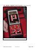
Figure 3 Out lined in red are the two places that will need to have solder added or removed. Figure 4 Just above the green cap 2A39 are two solder pads. The one that is circled is the one that is to be change.
Possible Mechanical Problems Panels Will Not Fit Doorway Try using an alternate doorway. If doorway is too large, use a 2" x 4" or a 2" x 3" block against the side of the panels, or panel width extenders to 48" (available from Retrotec). If the flow element rubs against the wall, door, or any other obstruction, try turning the panels upside down or contacting panels with another part of the door frame.
for leaks in the gauges by blowing in the tube, then folding the tube over on itself - the gauge should hold pressure without the needle dropping perceptibly. Occasionally, a needle will get stuck to the face plate. Replacing the gauge is the only practical option. Gauge Needle Falls When Tested Each time the Infiltrometer is used, the gauges should be pressured up, the tube capped off to test for leaks. A sudden loss of pressure will indicate something has changed.
Thermometer Replacement If the thermometer does not read correctly and cannot be adjusted with the control on front of the console, the entire assembly is removable and can be replaced by the operator. Call Retrotec. Fan Makes Scraping Noise When Turning Check to see if the blade hits the screen or the edge of the white plastic tube. Adjust the position of the motor by loosening two (2) bolts (1800 opposed) and adding or removing washers. Keep the total number of washers used the same.
The Retrotec Infiltrometer is warranted for two years parts and labor, except for the Hewlett Packard computer and Canon printer which are 90 days from the date of invoice. First 30 Days Retrotec will exchange components with major malfunctions (requiring factory repair) during the first 30 days from date of invoice. Retrotec will ship a new component to you by UPS ground. Return Phone the factory in Bellingham WA @ 360-738-9835 ext.303 (direct line to production) before returning anything for repair.