
User's Manual

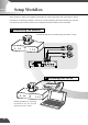

Setup Workflow
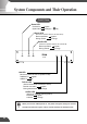
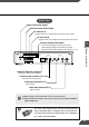
The procedure for setting up the VB150 and checking the video image begins with connecting the camera
to the VB150, connecting the VB150 to the PC via a hub and specifying the various settings. The next step
is to check that video from the camera can be displayed and that the camera can be controlled.
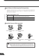
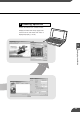
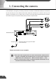
Connecting the camera1
V
C
-C
4
C
O
M
M
U
N
I
C
A
T
I
O
N
C
A
M
E
R
A
f
:
4
-
6
4
m
m
1
:
1
.
4
-
2
.
8
V
C
-
C
4
C
O
M
M
U
N
I
C
A
T
I
O
N
C
A
M
E
R
A
f
:4
-64
m
m
1:
1
.4
-2
.8
V
C
-
C
4
C
O
M
M
U
N
I
C
A
T
I
O
N
C
A
M
E
R
A
f:
4-
6
4
m
m
1
:1
.4
-
2
.8
Dc In 13V
In Out
100/10BT
CC1
RS232C
Video In
Ethernet
CC2 V1 V2 V3 V4
Slot-A
Slot-B
12 21
A B A B
V
C
-C
4
C
O
M
M
U
N
I
C
A
T
I
O
N
C
A
M
E
R
A
f
:
4
-
6
4
m
m
1
:
1
.
4
-
2
.
8
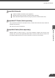
Initializing the VB1502
Connect the cameras to the VB150 using the cables (→ P.29).
Initialize the VB150 by connecting
the VB150 to the PC and the
network via a hub (→ P.30).
27