Network Camera VB-C500D Start Guide Please read carefully this Start Guide and the Operation Guide Especially be sure to read "Safety Precautions" before using the network camera. Keep this guide in a readily accessible location for future reference.
Introduction Thank you for purchasing Canon Network Camera VB-C500D (hereafter referred to as VB-C500D). This Start Guide describes how to set up and install the VB-C500D. The detailed procedures for using the VB-C500D are explained in the Operation Guide provided on the Setup CD-ROM. Read these guides carefully before using the VB-C500D to ensure that you make the best possible use of this product. Also, be sure to read "Safety Precautions" in this guide.
Introduction Trademark Notice Canon and the Canon logo are registered trademarks of Canon Inc. Microsoft Windows and Microsoft Internet Explorer are trademarks or registered trademarks of Microsoft Corporation in the United States and other countries. Windows is legally recognized as the Microsoft Windows Operating System. Other brands or product names in this guide are trademarks or registered trademarks of their respective companies.
Introduction MPEG-4 NOTICE ABOUT THE MPEG-4 VISUAL STANDARD: THIS PRODUCT IS LICENSED UNDER THE MPEG-4 VISUAL PATENT PORTFOLIO LICENSE FOR THE PERSONAL AND NONCOMMERCIAL USE OF A CONSUMER TO (i) ENCODING VIDEO IN COMPLIANCE WITH THE MPEG-4 VISUAL STANDARD ("MPEG-4 VIDEO") AND/OR (ii) DECODING MPEG-4 VIDEO THAT WAS ENCODED BY A CONSUMER ENGAGED IN A PERSONAL AND NONCOMMERCIAL ACTIVITY. NO LICENSE IS GRANTED OR SHALL BE IMPLIED FOR ANY OTHER USE.
Contents Introduction ..............................................................................................ii Checking of Bundled Items ....................................................................vii Operation Manuals .......................................................................................... viii How to Read This Document ..................................................................ix Symbols Used for Safety Precautions .................................................
Contents Chapter 2 Initial Setting and Installation of Camera Flow of Setup ....................................................................................... 2-2 Step 1 Install the Software ................................................................... 2-4 Install the Necessary Software ....................................................................... 2-4 Step 2 Connect the Camera to the Network ........................................
Checking of Bundled Items This product comes with the following items. If any item is missing, contact the store where you purchased the product. 1. VB-C500D main Unit 4. Setup CD-ROM 2. Safety wire 3. Ceiling mount template 5. Start Guide (This document) 6. Warranty Card (different depending on the region) Content of Setup CD-ROM ReadMe-J.txt : Japanese text covering notes, etc. not included in this document ReadMe-E.txt : English text covering notes, etc.
Checking of Bundled Items Operation Manuals The VB-C500D comes with Start Guide (this document) and Operation Guide included in the Setup CD-ROM. Start Guide (This Document) The safety precautions to be followed when using the VB-C500D, types of bundled software, operating environment, installation method, initial setting of the camera, installation method, etc., are explained. Operation Guide (VBC500DOG_E.
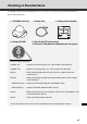
How to Read This Document In Start Guide and Operation Guide, screens in Windows Vista are mainly used. Unless otherwise specified, the same screens apply to Windows XP. Symbols Used for Safety Precautions In this document, the following symbols are used to indicate important items the user should know to use this product safely. Be sure to observe these items. Symbol Meaning Inappropriate handling against the instruction accompanied by this Warning symbol may result in death or injury.
Safety Precautions The following explains the items that must be observed when using the VB-C500D. If they are not observed, injury, death and/or property damage may occur. Read the following information carefully and observe the instructions without fail. Important Warnings CAUTION TO REDUCE THE RISK OF ELECTRIC SHOCK, DO NOT REMOVE COVER (OR BACK). NO USER-SERVICEABLE PARTS INSIDE. REFER SERVICING TO QUALIFIED SERVICE PERSONNEL.
Safety Precautions FCC NOTICE Network Camera, Model Name: VB-C500D This device complies with Part 15 of the FCC Rules. Operation is subject to the following two conditions: (1) This device may not cause harmful interference, and (2) this device must accept any interference received, including interference that may cause undesired operation. Note: This equipment has been tested and found to comply with the limits for a Class B digital device, pursuant to Part 15 of the FCC Rules.
Safety Precautions Precautions for Installation Warning Do not install the product in the following places: • Place receiving strong direct sunlight, near heat generating objects, or subject to high temperature • Place near fire sources or flammable solvents (alcohol, thinner, etc.) • Humid or dusty place • Place subject to lamp black or steam • Place subject to sea wind • Narrow, sealed place Fire or electric shock may result.
Safety Precautions Precautions for Use Warning • If smoke, abnormal noise, heat, odor or any other abnormality is detected, immediately stop using the camera and contact your nearest Canon dealer. Continuing to use the product may result in fire or electric shock. • Do not disassemble or modify the camera. • Do not put water or other liquid in the camera or splash or otherwise wet the camera. • Do not put foreign objects in the camera. • Do not use sprays of flammable gases near the camera.
Safety Precautions Notes on Use of Motion Detection, Stream for Recording and Bundled Recording Software VK-Lite Note • Avoid using Motion Detection, Stream for Recording or recording software VK-Lite for surveillance where very high level of reliability is constantly required. These are support functions for monitoring. They do not guarantee monitoring with very high accuracy, however, as they might not work as accurately as expected under certain conditions.
Safety Precautions Maintenance Turn off the power before cleaning the camera ( P. 2-7). Cleaning of Exterior 1. Dampen a soft cloth with water or diluted neutral detergent and wipe the soiled areas gently. 2. Wipe with a dry cloth. Cleaning of Lens Use a commercial lens cleaner to remove soiling on the lens surface. Scratches on the lens surface may result in undesirable images. Maintenance for Dome Case A soiled dome is a cause of poor image quality, so clean the dome periodically. 1.
Safety Precautions xvi
Before Use The following explains the features of this camera, bundled software, operating environment, and name and function of each part.
Features of VB-C500D The VB-C500D is a compact network camera for indoor installation integrating camera and server features. Wide-angle Varifocal Lens Equipped with a wide-angle varifocal lens with a wide angle of 82°, F1.1 and optical 2.4x zoom (digital 4x), the VB-C500D achieves video monitoring in wide-ranging applications, including stores and offices, as well as applications in small areas such as at ATM and in elevator halls.
Features of VB-C500D Install-Less VB-C500 Viewer This camera has a built-in VB-C500 Viewer, so its data can be viewed using a browser. Accordingly, there is no need to install a PC application. Also, three levels of user privileges can be set, including [Administrator], [Authorized Users] and [Guest Users].
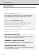
Features of VB-C500D Two-Way Audio (Full Duplex) A microphone or speaker with amplifier can be connected*1 to the camera to transmit/receive audio (full duplex) via the viewer*2. You can select a desired audio input mode from LINE IN and MIC IN by switching the setting on the setting page ( P. 3-7). *1 Microphones and amplifiers are sold separately. *2 VK-Lite Viewer is the only viewer that supports two-way audio communication. VB-C500 Viewer only supports audio reception.
Bundled Software The VB-C500D comes with the software specified below. For the latest information on this product (firmware, bundled software, operation manuals, 1 operating environment, etc.), visit our website. Before Use VB Initial Setting Tool Ver. 5.0 ( P. 2-10) VB Initial Setting Tool is for initial setting of the VB-C500D. It is installed from Setup CD-ROM ( P. 2-4). Users other than Administrators need not install this tool. VBAdmin Tools Ver. 5.
Bundled Software VB-C500 Viewer Ver. 1.0 ( Overview of VB-C500 Viewer in Operation Guide) VB-C500D Viewer is for displaying video captured by this camera and controlling the camera. Three users can be set according to the camera control rights, including [Administrator], [Authorized Users] and [Guest Users]. This tool is already built into the camera and need not be installed beforehand ( P. 2-4). JPEG video captured by the VB-C500D can be displayed. To display MPEG-4 video, install VK-Lite Viewer ( P.
Bundled Software Software Configuration of VK-Lite Overview VK-Lite Storage Server Up to four cameras can be registered to record video. 1 License Before Use Type 1 license Recorded video saved in the storage server can be VK-Lite Viewer played or live video (JPEG/MPEG-4) can be displayed as it is captured by the camera. Up to four cameras can be 1 license registered for the viewer. VK-Lite Storage Server and VK-Lite Viewer can also be installed in, and run on, the same PC.
Bundled Software Key Functional Limitations of VK-Lite and VK-64/VK-16 Category Camera connection Key functional limitation VK-Lite v2.1 VK-64/VK-16 v2.
Bundled Software Note For details on the operating methods and function limitations pertaining to VK-Lite, refer to the Setup Guide and Administrator’s Manual. Before Use Tip With VK-Lite, multiple storage servers cannot be registered. However, this function can be utilized if the optional VK-64 Viewer is used. Up to 10 units of VK-Lite Storage Server can be centrally managed and operated. Comparison of Two Viewers The VB-C500D has two viewers. The key differences are specified below.
Bundled Software VK-Lite Viewer Audio Transmission/Reception (Two-way Communication) VB-C500D Microphone (sold separately) JPEG/MPEG-4 VK-Lite Viewer Speaker (sold separately) Audio Audio can be transmitted/received between the VB-C500D and viewer. Tip PC, speaker and microphone are sold separately.
Operating Environment For the latest information on this product (firmware, bundled software, operation manuals, operating environment, etc.), visit our website. OS and browser Viewer display Audio Windows Vista Home Premium/Business/Enterprise/Ultimate (SP1), Internet Explorer 7.0 Windows Server 2008 Standard Internet Explorer 7.0 Windows Server 2003 R2 Standard Edition (SP2), Internet Explorer 6.0 (SP2)/7.0 Windows Server 2003 Standard Edition (SP2), Internet Explorer 6.0 (SP2)/7.
Operating Environment *1 Windows Vista and Windows Server 2008 support the 32-bit and 64-bit editions. Other OSs support only the 32-bit edition. *2 External hard disks cannot be used. Tip The optional VK-64/VK-16 v2.1 does not support Windows Vista Home Premium.
Notes on Operating Environment Notes on Use When the [Windows Firewall] Function is Enabled 1 If the [Windows Security Alert] dialog box appeared, click [Unblock]. Once this button is clicked, this warning dialog box will no longer appear. If the [Windows Security Alert] dialog box is not displayed, the warning function of the Windows firewall may be disabled. Follow the procedure below to add [VB Initial Setting Tool] as an exception to the Windows Firewall. 1.
Notes on Operating Environment 3. Click the [Add program…] button to add [VB Initial Setting Tool]. Notes on Use with Windows Server 2003/Windows Server 2008 Registering the Camera's Top page as a Trusted Site In Windows Server 2003 and Windows Server 2008, the security level for Internet sites and intranet sites on Internet Explorer is set to [High] by default.
Notes on Operating Environment 2. Clicking [Add] opens the Trusted sites dialog box. Clear the [Require server verification (https:) for all sites in this zone] check box, if currently selected. 1 Before Use 3. Enter the IP address of the VB-C500D under [Add this Web site to the zone], and then click [Add] to register the site as a trusted site. For details on registering trusted sites, click the [Learn more about Internet Explorer’s Enhanced Security Configuration...
Notes on Operating Environment 3. Select [Trusted Sites], and click [Site]. This completes the process of registering the camera's top page as a trusted site. Notes on Use with Windows Server 2008 Enabling the Sound Function to Use Audio In Windows Server 2008, the sound function is disabled by default. If you want to receive audio on VB-C500 Viewer, enable the sound function by following the procedure below. 1. Click [Control Panel] and select [Hardware and Sound].
Notes on Operating Environment Tip If [Control Panel] is displayed in a classic view, double-click [Sound]. Before Use 2. 1 Next, click [Sound]. 3. When the dialog box with the message, [Audio Service is not running] appears, click [Yes]. 4. Finally, the [Sound] dialog box appears. Click the [Playback] tab to confirm that an audio device has been installed. (If no audio device is installed, check the manual for you PC.
Notes on Operating Environment Notes on Use with Windows Vista The following restrictions apply when the VB-C500D is used with Windows Vista Home Premium/ Business/Enterprise/Ultimate. Network Video Recorder VK-Lite v2.1 Warning dialog box displayed upon opening of the [Storage Server Settings] dialog box If the User Account Control is enabled in Windows Vista, the User Account Control dialog box appears when the Storage Server Settings tool is started.
Notes on Operating Environment Name and Function of Each Part 1 Before Use Dome Case/Inner Cover/Camera Interior Dome case Inner cover Varifocal lens Horizontal field of view 82° Focus lock screw Zoom adjustment knob Rotation lock screw Pan lock screw Tilt lock screw Dome case lock screw 1-19
Notes on Operating Environment Top View of Camera (Without Dome Case) Reset switch Turn on the power while pushing this switch. Continue to push the switch for 5 seconds or more to restore all factory settings except for the date and time. LED The LED becomes lit/unlit according to the status of the camera. (1) Installation mode: Lit ( P.
Notes on Operating Environment Bottom The MAC address and serial number required in network setting are specified at the bottom of the camera. Write down these information before installing the camera. 1 Before Use Serial number Serial number of this camera. Tripod mounting screw holes MAC address Unique address of this camera. Write down this address before installing the camera ( P. 2-10). LAN connector Conforming to 100Base-TX PoE power supply (conforming to the IEEE 802.
Optional Items Purchase options separately as necessary. Audio Interface Cable WA500-VB Use this interface cable to connect the camera to an audio input/output device (speaker, microphone, etc.). Marking band OUT IN The terminal marked "1" on the marking band (farther away from the cable branching point) is used for audio output, while the unmarked terminal (closer to the branching point) is used for audio input. For details on the audio input/output terminals, refer to P. 3-7.
Optional Items I/O Interface Cable WC500-VB Use this interface cable to connect the camera to a contact input/output device (sensor, warning 1 Before Use lamp, etc.). For details on the external device input/output terminals, refer to P. 3-5. Power Interface Cable WP500-VB Use this interface cable to connect the camera to an optional AC adapter (PA-V17) or external power supply. For use of an AC adapter or external power supply, refer to P. 2-9.
Optional Items Recessed Mounting Kit SR500-S-VB The Recessed Mounting Kit is a dedicated option for VB-C500D. Use example AC Adapter PA-V17 Use this adapter when a PoE HUB or external power supply is not used. VK-Lite Additional Viewer License VK-Lite Additional Viewer License is an additional license needed to install VK-Lite Viewer to each PC. You need to purchase the license if you want to view video captured by the camera using VK Viewer from multiple sites.
Optional Items Network Video Recorder VK-64/VK-16 v2.1 1 High-functional monitoring & recording software that achieves simultaneous monitoring of Before Use multiple sites. Example of VK-64/VK-16 Viewer screen Note VB-C500D cannot be used with an old version of VK-64/VK-16. If you are using an old version, update it to the new version. For details, visit our website. Tip This camera comes with VK-Lite v2.1, which is a simplified version of VK-64/VK-16 v2.1 ( P. 1-6).
Optional Items 1-26
Initial Setting and Installation of Camera The following explains how to install the camera. First, install the necessary software from the bundled Setup CD-ROM. Next, connect the camera to the network and perform initial setting of the camera. Check the video using VB-C500 Viewer, and then install the camera. Before installing the camera, be sure to set the IP address.
Flow of Setup Step 1 Install the software Insert the bundled Setup CD-ROM in the PC and install the necessary software ( P. 2-4). PC Bundled Setup CD-ROM Step 2 Connect the camera to the network Connect the VB-C500D and PC to the network ( P. 2-6). If a PoE HUB or Midspan is used, consult your Canon sales representative. VB-C500D LAN cable PC PoE HUB The figure shows connection via a PoE HUB.
Flow of Setup Step 3 Perform initial setting of the camera Start VB Initial Setting Tool and perform initial setting of the camera ( P. 2-10). Check the image using VB-C500 Viewer ( P. 2-13). Step 4 Initial Setting and Installation of Camera VB Initial Setting Tool window VB-C500 Viewer Install the camera Install the VB-C500D securely ( P. 2-15).
Step 1 Install the Software Install the Necessary Software First, install the necessary software from the bundled Setup CD-ROM ( P. 1-5). Software for Initial Setting and Management of the Camera Type VB Initial Setting Tool Overview This tool is used to perform initial setting of the camera ( P. 2-10). Users other than Administrators need not install this tool. This tool is used to manage the camera ( Chapter 2 in Operation VBAdmin Tools Guide).
Step 1 Install the Software At this time, be sure to install VB Initial Setting Tool required in initial setting of the camera. 1. Insert Setup CD-ROM bundled with the camera in the CD-ROM drive of the PC, and perform the following procedure. (1) After confirming that all other applications have been closed, click the [Start] menu and then select [My Computer]. Initial Setting and Installation of Camera (2) Double-click the displayed CD-ROM icon VBTools Folder and then click VBToolsInstall.exe. 2.
Step 2 Connect the Camera to the Network Connect the Camera to the Network and Turn On the Power Here, an example of connecting one camera to a PC via a HUB is explained. VB-C500D comes with a PoE (Power over Ethernet). The power can be supplied to the camera, via a LAN cable, from a PoE HUB conforming to IEEE 802.3af. Via PoE HUB LAN cable (Back) PoE HUB Notebook PC AC power cable If an AC adapter (optional) or external power supply is used, connect it as shown below.
Step 2 Connect the Camera to the Network Tip When connecting an AC adapter (optional), unplug the connector at the end of the output cable for AC adapter and connect the wires to the power interface cable. The power interface cable can be connected with no polarity. If the power is supplied by the PoE via a LAN cable on the VB-C500D, disconnect and connect the LAN cable to the HUB receiving the power, to turn the power "ON"/"OFF.
Step 2 Connect the Camera to the Network Note When turning off the power and then turning it back on, wait for at least 5 seconds before turning on the power. If the power is turned on too quickly, the camera may not operate correctly. Also, when disconnecting/connecting the power connection, be sure to observe the instructions provided in "Safety Precautions/Notes on AC Adapter (Optional)" ( P. xiv). • The current may be limited for each port depending on the PoE HUB used.
Step 2 Connect the Camera to the Network Use of External Power Supply Connect the bundled power interface cable (WP500-VB) as shown below. Screwdriver Tightening torque: 0.4N·m (3.54lbf·in) (max.) Initial Setting and Installation of Camera Stripping length Power interface cable Approx. 5 mm (0.20 in) AC adapter Use a 12-VDC or 24-VAC power supply insulated from 100 VAC.· 12 VDC can be connected in a non-polar condition. Use the power supply within the following voltage range.
Step 3 Perform Initial Setting of the Camera Perform Initial Setting of the Camera Set the network for the VB-C500D using VB Initial Setting Tool. 1. Launches VB Initial Setting Tool. Double-click the [VB Initial Setting Tool v5.0] icon on the desktop, or click the [Start] menu, click [Programs], click [Webview Livescope], and then select [VB Initial Setting Tool v5.0]. Double-click the icon on the desktop. 2.
Step 3 Perform Initial Setting of the Camera 3. Enter the user name "root" and default password "camera," and then enter the IP address and subnet mask you want to set. Note There may be cautionary information that should be heeded depending on your operating environment. Before the initial setting, refer to "Notes on Operating Environment" ( P. 1-13). Tip The factory-set Administrator password is "camera.
Step 3 Perform Initial Setting of the Camera Note To set the IP address from the DHCP server, set an address from VB Initial Setting Tool to enable communication with the setup PC and change the setting of [IP Address Setting] under [Network] ("LAN" in Operation Guide) on the Setting page to [Auto (DHCP)]. The camera will stop issuing IP address assignment requests in 20 minutes after its power is turned on, upon which detection by VB Initial Setting Tool will be disabled.
Step 3 Perform Initial Setting of the Camera Check the Video Captured by the Camera When the initial setting is complete, check the video captured by the camera using VB-C500 Viewer. At this time, set the network options on the PC according to the IP address and subnet mask set in the camera. Click to select. 2. The web browser starts and the top page of the camera is displayed. Click [VB Viewer] from [VB-C500 Viewer].
Step 3 Perform Initial Setting of the Camera 3. The viewer starts and video captured by the camera is displayed. Note Clicking [Setting Page] or [Admin Viewer] on the top page of the camera displays each user authentication window.
Step 4 Install the Camera Note on Use before Installing the Camera Be sure to install the camera after setting the IP address ( P. 2-10). Note The camera will stop issuing IP address assignment requests in 20 minutes after its power installing the camera, set the IP address and check the operation by referring to "Perform Initial Setting of the Camera" ( P. 2-10). The unique MAC address of this camera is specified at the bottom of the camera ( P. 1-21).
Step 4 Install the Camera Installation Procedure for Direct Mounting on a Ceiling/Wall Side View of mounting Roof space Audio interface cable Safety Wire Fix to an anchor or structure Connect to a microphone Connect to a speaker I/O interface cable Connect to an external device Power interface cable Connect to an AC adapter or external power supply Connect to the network LAN cable Ceiling board VB-C500D 1. Use the bundled template to determine the installation position of the camera.
Step 4 Install the Camera 2. Remove the dome case and cable cover from the camera. • To remove the dome case, loosen the two screws on the side face of the camera. Loosen the screws until they project. • To connect various interface cables (audio, I/O, power), remove the cable cover lock screw at the bottom of the camera. Initial Setting and Installation of Camera Dome case lock screw Note When removing the dome case, be careful not to scratch or dirty the dome. 3.
Step 4 Install the Camera 4. Connect each interface cable. • This process is not required if you don't use any microphone, sensor, AC adapter or external power supply. • Select an appropriate interface cable according to the external device used, and connect the cable to the camera. • The interface cables and camera have dedicated connectors and connection terminals, respectively. • You can select a desired direction from which to take out the interface cables and other wirings.
Step 4 Install the Camera Note Observe the following items when connecting the interface cables. • Firmly insert the dedicated terminals on the audio interface cable into the audio input/output terminals on the camera. Affixing groove for cable Power Affixing groove for cable Initial Setting and Installation of Camera • Affix each interface cable in the specified groove, as shown below.
Step 4 Install the Camera Wiring on a Ceiling Cut out the side face of the cover. Power interface cable Audio interface cable I/O interface cable If the wirings cannot be concealed in the ceiling, cut out the V-groove in the cable cover and take out the wirings from the side face of the camera, and then affix the cable cover with screws. Cut out the V-groove. For the types of interface cables, refer to the page on Optional Items ( P. 1-22).
Step 4 Install the Camera Note Observe the following items when connecting the interface cables. • Firmly insert the dedicated terminals on the audio interface cable into the audio input/output terminals on the camera. Affix the interface cables in the specified grooves, respectively, in the order of Initial Setting and Installation of Camera • power supply, audio and I/O, as shown below.
Step 4 Install the Camera 5. Connect the LAN cable, and also connect each external device using a cable. Connect the LAN cable that has been guided through the wiring hole, to the LAN cable on the camera side. If necessary, connect the audio, I/O or power interface cable to each external device. 6. Affix the camera on the ceiling.
Step 4 Install the Camera • Next, loosen the focus lock screw. • Adjust the viewing angle and focus using the zoom adjustment knob and focus ring. When the adjustment is complete, tighten the focus lock screw to lock the focus. Pan lock screw Rotation lock screw Zoom adjustment knob Focus lock screw Focus Adjustment Method To adjust the focus, press the reset switch to enter the installation mode. Accurate focus adjustment can be performed in the installation mode.
Step 4 Install the Camera Tip Image from the network is disconnected when you switch to the installation mode (when the reset switch is pressed) or return to a normal mode from the installation mode. In the installation mode, the camera cannot be controlled. Only NTSC is supported for video output. The LED remains lit in the installation mode, and a white square is shown on the bottom left of the screen. 8. Install the inner cover and dome case.
Step 4 Install the Camera Installation Procedure for In-Ceiling with a Ceiling/Wall Side View of mounting Roof space Fix to an anchor or structure Connect to a microphone Connect to a speaker I/O interface cable Initial Setting and Installation of Camera Audio interface cable Safety Wire Connect to an external device Power interface cable Connect to an AC adapter or external power supply Connect to the network LAN cable In-Ceiling bracket Backside ceiling bracket Recessed Mounting Cover VB-C500D
Step 4 Install the Camera 2. Use the template supplied with the Recessed Mounting Kit to determine the installation position of the camera. Confirm the capturing direction of the camera, and then use the supplied template to open holes for the Backside Ceiling Bracket and in-ceiling bracket. 3. Install the assembled in-ceiling bracket at the back of the ceiling/wall and secure it with screws. 4.
Step 4 Install the Camera 5. Affix the assembled in-ceiling bracket assembled with the camera, on the installation surface. Hook the assembled in-ceiling bracket on the screws that were loosely secured in step 3, turn the bracket clockwise, and securely tighten (affix) the screws. Initial Setting and Installation of Camera 6. Adjust the camera angle and focus in the same manner as in step 7 of "Installation Procedure for Direct Mounting on a Ceiling/Wall," and install the dome case. 7.
Step 4 Install the Camera 2-28
Appendix This section explains the external dimensions, specifications, external device input/output terminals, audio input/output terminals, etc.
External Dimension Drawing 64mm (2.52 in) 136mm (5.35 in) 95mm ( 3.74 in) VB-C500D 4- 4.6mm (0.16- 0.18 in) 108mm (4.25 in) 110mm (4.33 in) 148mm (5.83 in) mm 169 ( utsid ):O 5 in 6.6 27mm (1.06 in) 63mm (2.48 in) Recessed Mounting Kit SR500-S-VB (Option) n) 4i r ete iam ed 3- 5.0mm (0.12- 0.20 in) m 0° 4m 112mm (4.41 in) 64mm (2.52 in) 19 120° 98mm (3.86 in) 215mm (8.46 in) 12 8-M4.0mm (0.31-M0.16 in) 76mm (2.99 in) 110mm (4.33 in) 3-2 ( 7.
Main Specifications VB-C500D Image sensor 1/4-inch CCD (primary color filter) Number of pixels Effective pixels: 310,000 pixels Scanning method Progressive method Lens Varifocal lens: Optical 2.4x zoom lens (digital 4x) Focus length f=2.6 to 6.2mm F-value F1.1 (W end) to F1.4 (T end) Viewing angle Horizontal field of view: 82° (W end) to 34° (T end) Vertical viewing angle: 60.5° (W end) to 25.5° (T end) Day/night capability Auto/manual switching Day mode : 0.2 lux (F1.
Main Specifications VB-C500D (Continued) Network terminal LAN-1 (RJ45, 100Base-TX (Auto/Full Duplex/Half Duplex)) Audio input terminal (Used as both LINE IN and MIC IN) Φ3.5 monaural mini jack connector * Connection via an audio interface cable LINE IN-1 (connected to a microphone with amplifier) or MIC IN-1 (connected to a microphone without amplifier) (LINE IN and MIC IN can be switched on the setting page) Audio output terminal (LINE OUT) Φ3.
Input/Output Terminals The various input/output terminals of the camera are located inside the cable cover at the bottom of the camera. To connect the camera to an audio input/output device, contact input/output device, AC adapter or external power supply, open the cable cover and connect the device using a dedicated interface cable. All interface cables come with dedicated terminals for connection with the camera. Check the shape of each terminal thoroughly and insert the terminal in the correct direction.
Input/Output Terminals Color of spare wire Type of corresponding terminal Color of spare wire Type of corresponding terminal 1 Black OUT2_B 5 Yellow IN2_- 2 Brown OUT2_A 6 Green IN2_+ 3 Red OUT1_B 7 Blue IN1_- 4 Orange OUT1_A 8 White IN1_+ External Device Input Terminals (IN1, IN2) There are two sets of external device input terminals (IN1, IN2), where each set consists of two terminals. The - terminals are connected to the GND in the camera.
Input/Output Terminals Internal Connection Diagram +3.3V 10kΩ 10kΩ 10kΩ + External device Internal controller 0.1µF Input terminal: IN1, IN2 – Appendix External device Output terminal: OUT1, OUT2 Tip Applicable wire for external device cable Single wire of AWG No. 28 to 22 Conductor size Φ0.32 to 0.65 mm (Φ0.013 to 0.026 in) Strip the cable by approx. 8 to 9 mm (0.31 to 0.35 in) Audio Input/Output Terminals One audio input terminal and one audio output terminal is available.
Input/Output Terminals input. Switch the input mode on the Setting page ("Audio Input" in Operation Guide). The factory setting is LINE IN. When LINE IN is selected, a microphone with amplifier can be connected. When MIC IN is selected, a dynamic microphone or capacitor microphone can be connected. Input terminal: Φ3.5-mm mini jack (monaural) • Dynamic MIC IN setting Input impedance: 1.
Input/Output Terminals Note Switch the LINE IN/MIC IN setting on the Setting page according to the microphone specification ("Audio Input" in Operation Guide). If a wrong input is used, the camera or microphone may be damaged. Be sure to set the correct input. The volume, sound quality, etc., may change depending on the characteristics of the microphone used. To send audio to speaker, use VK-Lite Viewer. Audio cannot be sent from VB-C500 Viewer Video and audio may sometimes lose synchronism.
CANON INC. 30-2, Shimomaruko 3-chome, Ohta-ku, Tokyo 1468501, Japan CANON EUROPA N.V. Bovenkerkerweg 59-61, P.O. Box 2262, 1185 XB Amstelveen, The Netherlands CANON U.S.A.,INC. One Canon Plaza Lake Success, NY 11042-1198 USA CANON EUROPE LTD. 6 Roundwood Avenue, Stockley Park, Uxbridge Middlesex, UB11 1JA, United Kingdom • CANON COMMUNICATION & IMAGE FRANCE 12 Rue De L’lndustrie, 92414 Corbevoie, Cedex, France If you have any questions, call the CANON U.S.A.