NETWORK CAMERA Start Guide Be sure to read Start Guide and Operation Guide before using. In particular, be sure to read the "Safety Precautions" section and use the camera correctly. Keep this guide in a readily accessible location for future reference.
Introduction Thank you for purchasing Canon Network Camera VB-C60/VB-C60B (hereafter referred to as VB-C60). The only difference between VB-C60 and VB-C60B is the exterior color. This Start Guide describes the initial settings and mounting method of the VB-C60. The detailed procedures for using the VB-C60 are explained in the Operation Guide provided on the bundled Setup CD-ROM. Read these guides carefully before using the VB-C60 to ensure that you make the best possible use of this product.
Introduction Notes on Network Security The user is responsible for the network security of this product and its use. Take appropriate network security measures to avoid security breaches. To the full extent permitted by laws and regulations, neither Canon Inc. nor any of its subsidiaries or affiliates shall be liable for any losses, direct, incidental or consequential damages, or liabilities that may be incurred as a result of network security incidents such as unauthorized accesses.
Introduction Notes on privacy and publicity rights regarding the utilization of video/audio When using the VB-C60 (for video or audio recording), it is the responsibility of the users to take all care to protect privacy and avoid any violation of publicity rights. Canon shall have no liability whatsoever in this regard.
Introduction Notes on License Agreement for Bundled Software See the following files in the BundledSoftware folder inside the LICENSE folder of the bundled Setup CD-ROM for information regarding the license agreement for bundled software. Software Type File Name VB Initial Setting Tool, VBAdmin Tools VBTools.txt Network Video Recording Software RM-Lite RM-Lite.txt European Union (and EEA) only.
Introduction MPEG-4 NOTICE ABOUT THE MPEG-4 VISUAL STANDARD: THIS PRODUCT IS LICENSED UNDER THE MPEG-4 VISUAL PATENT PORTFOLIO LICENSE FOR THE PERSONAL AND NONCOMMERCIAL USE OF A CONSUMER TO (i) ENCODING VIDEO IN COMPLIANCE WITH THE MPEG-4 VISUAL STANDARD ("MPEG-4 VIDEO") AND/OR (ii) DECODING MPEG-4 VIDEO THAT WAS ENCODED BY A CONSUMER ENGAGED IN A PERSONAL AND NONCOMMERCIAL ACTIVITY. NO LICENSE IS GRANTED OR SHALL BE IMPLIED FOR ANY OTHER USE.
Introduction vii
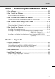
Contents Introduction ..............................................................................................ii Checking of Bundled Items ..................................................................... x Operation Manuals ............................................................................................ xi How to Read This Document .................................................................xii Symbols Used for Safety Precautions .................................................
Contents Chapter 2 Initial Setting and Installation of Camera Flow of Setup ....................................................................................... 2-2 Step 1 Install the Software ................................................................... 2-4 Install the Necessary Software ....................................................................... 2-4 Step 2 Connect the Camera to the Network ........................................
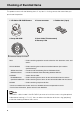
Checking of Bundled Items This product comes with the following items. If any item is missing, contact the store where you purchased the product. 1. VB-C60 or VB-C60B Camera 2. Power connector 3. Rubber feet (4 pcs) 4. Setup CD-ROM 5. Start Guide (This document) 6.
Checking of Bundled Items Operation Manuals The VB-C60 comes with Start Guide (this document) and Operation Guide included in the Setup CD-ROM. Start Guide (This Document) The safety precautions to be followed when using the VB-C60, types of bundled software, operating environment, mounting method, initial setting of the camera, etc., are explained. Operation Guide (VBC60OG_E.
How to Read This Document The screenshots used in the Start Guide and Operation Guide are mainly from Windows Vista and Windows 7. Unless otherwise specified, the same screens apply for other operating systems. Symbols Used for Safety Precautions The symbols used in this document are explained. This document uses the following symbols to indicate the important information the user should know in order to use the product safely. Be sure to observe these items.
Safety Precautions The following explains the items that must be observed when using the VB-C60. If they are not observed, injury, death and/or property damage may occur. Read the following information carefully and observe the instructions without fail. Important Warnings CAUTION TO REDUCE THE RISK OF ELECTRIC SHOCK, DO NOT REMOVE COVER (OR BACK). NO USER-SERVICEABLE PARTS INSIDE. REFER SERVICING TO QUALIFIED SERVICE PERSONNEL. The AC adapter can be connected to VB-C60 from a standard AC power outlet.
Safety Precautions FCC NOTICE Network Camera, Model Name: VB-C60 This device complies with Part 15 of the FCC Rules. Operation is subject to the following two conditions: (1) This device may not cause harmful interference, and (2) this device must accept any interference received, including interference that may cause undesired operation. Note: This equipment has been tested and found to comply with the limits for a Class B digital device, pursuant to Part 15 of the FCC Rules.
Safety Precautions Precautions for Installation Warning Do not install the product in the following places: • Place receiving strong direct sunlight, near heat generating objects, or subject to high temperature • Place near fire sources or flammable solvents (alcohol, thinner, etc.) • Humid or dusty place • Place subject to lamp black or steam • Place subject to sea wind • Narrow, sealed place Fire or electric shock may result.
Safety Precautions Precautions for Use Warning • If smoke, abnormal noise, heat, odor or any other abnormality is detected, immediately stop using the camera and contact your nearest Canon dealer. Continuing to use the product may result in fire or electric shock. • Do not disassemble or modify the camera. • Do not put water or other liquid in the camera or splash or otherwise wet the camera. • Do not put foreign objects in the camera. • Do not use sprays of flammable gases near the camera.
Safety Precautions Notes on Use of Motion Detection, Stream for Recording and Bundled Recording Software RM-Lite Note • Avoid using Motion Detection, Stream for Recording or recording software RM-Lite for surveillance where very high level of reliability is constantly required. These are support functions for monitoring. They do not guarantee monitoring with very high accuracy, however, as they might not work as accurately as expected under certain conditions.
Safety Precautions Maintenance Turn off the power before cleaning the camera ( P. 2-6). Cleaning of Exterior 1. Dampen a soft cloth with water or diluted neutral detergent and wipe the soiled areas gently. 2. Wipe with a dry cloth. Cleaning of Lens Use a commercial lens cleaner to remove soiling on the lens surface. Auto focus may not work properly if the lens surface is dusty or dirty. Scratches on the lens surface may result in undesirable images.
Before Use The following explains the features of this camera, bundled software, operating environment, and name and function of each part.
Features of VB-C60 The VB-C60 is a compact network camera integrating camera and server features. Optical 40x Zoom Lens with Auto Focus and Pan and Tilt functions Equipped with a lens with optical 40x zoom (digital 4x), VB-C60 achieves video monitoring in wide-ranging applications including in indoor locations such as stores and offices, as well as in outdoor areas such as parking lots and plant facilities.
Features of VB-C60 Image Stabilizer This function compensates for shaking of image due to vibration when the camera is installed on the ceiling, on a pole, etc. See "Camera Control" ( Operation Guide). Install-Free VB-C60 Viewer This camera has a built-in VB-C60 Viewer, so its data can be viewed using a browser. Accordingly, there is no need to install a PC application. Also, three levels of user privileges can be set, including [Administrator], [Authorized Users] and [Guest Users].
Features of VB-C60 Supporting Upright and On-the-ceiling Installation You can install the camera in a stationary state (upright) on a table or on a ceiling* (on the ceiling) by changing the settings ( "Installation Conditions" in Operation Guide). * The camera cannot be installed in locations exposed to direct sunlight, high temperature, high humidity, etc. ( P. xv). When installing the camera on a ceiling, use the optional indoor dome housing or ceiling mount cover ( P. 1-21).
Bundled Software The VB-C60 comes with the software specified below. For the latest information, please refer to Canon Web Site. 1 ( P. 2-10) Perform initial settings of the camera. Install it from Setup CD-ROM ( P. 2-4). Users other than Administrators need not install this tool.
Bundled Software VBAdmin Tools ( "Overview of VBAdmin Tools" in Operation Guide) This tool lets you create panorama images with the camera and use these images to visually set the view range and presets. VBAdmin Tools are for setting motion detection and for displaying logs taken by the camera. Install it from Setup CD-ROM ( P. 2-4). Users other than Administrators need not install this tool.
Bundled Software VB-C60 Viewer ( "Overview of VB-C60 Viewer" in Operation Guide). VB-C60 Viewer is for displaying video captured by this camera and controlling the camera. On [Administrator], [Authorized User] and [Guest User] and restrict the control privileges of [Authorized User] and [Guest User]. VB-C60 Viewer is already built into the camera and need not be installed beforehand ( P. 2-4). Only JPEG images can be displayed. To display MPEG-4 video, install and use RM-Lite Viewer ( P. 1-8).
Bundled Software Software Configuration of RM-Lite Type Overview RM-Lite Storage Server Up to four cameras can be registered to record video. License 1 license Recorded video saved in the storage server can be played or live video (JPEG/MPEG-4) can be displayed RM-Lite Viewer as it is captured by the camera. 1 license Up to four cameras can be registered for the viewer. RM-Lite Storage Server and RM-Lite Viewer can be installed in and run on the same PC.
Bundled Software Key Functional Limitations of RM-Lite and RM-64/RM-25/RM-9 Features RM-Lite 1 RM-64/RM-25/RM-9 Before Use Connecti on to camera Max. number of cameras 4 64/25/9 Storage Server Recording formats JPEG only JPEG, MPEG-4, H.264 Max.
Bundled Software Comparison of Two Viewers The VB-C60 has two viewers. The key differences are specified below.
Operating Environment For the latest information, please refer to Canon Web Site.
Operating Environment Network Video Recording Software RM-Lite CPU OS Memory Hard disk Viewer display Audio Intel XEON 3060 2.4 GHz, Intel Core 2 Duo 2.4 GHz or higher, or an Intel CPU of equivalent class that meets the following requirements. Clock: 2.
Notes on Operating Environment Notes on Use When the [Windows Firewall] Function is Enabled 1 Before Use When VB Initial Setting Tool is started, the [Windows Security Alert] dialog box may appear. If the [Windows Security Alert] dialog box appeared, click [Unblock]. Once this button is clicked, this warning dialog box will no longer appear. If the [Windows Security Alert] dialog box is not displayed, the warning function of the Windows firewall may be disabled.
Notes on Operating Environment 3. The [Add a Program] dialog box appears. Click to select [VB Initial Setting Tool], and then click [OK]. Notes on Use with Windows Server 2003/Windows Server 2008 Registering the Camera's Top page as a Trusted Site In Windows Server 2003 and Windows Server 2008, the security level for Internet sites and intranet sites on Internet Explorer is set to [High] by default.
Notes on Operating Environment 2. The [Trusted Sites] dialog box appears. Clear the [Require server verification (https:) for all sites in this zone] check box, if currently selected. 1 Before Use 3. Enter the IP address of the camera under [Add this Web site to the zone], and then click [Add]. For details on registering trusted sites, click the [Learn more about Internet Explorer's Enhanced Security Configuration...] in the dialog box in Procedure 1 and see the displayed overview.
Notes on Operating Environment 3. Click and select [Trusted Sites], and click [Sites]. The [Trusted Sites] dialog box appears. This completes the process of registering the camera's top page as a trusted site. Notes on Use with Windows Server 2008 Enabling the Sound Function to Use Audio In Windows Server 2008, the sound function is disabled by default. To receive audio with VB-C60 Viewer, follow the procedure below to enable the sound function. 1. Click [Control Panel] and select [Hardware and Sound].
Notes on Operating Environment Tip If [Control Panel] is displayed in a classic view, double-click [Sound]. Before Use 2. 1 Click [Sound]. 3. The message, [Audio Service Not Running] appears. Click [Yes]. 4. The [Sound] dialog box appears. Click the [Playback] tab to confirm that an audio device has been installed. (If no audio device is installed, check the manual for your PC.
Notes on Operating Environment Notes on Use with Windows Vista or Later The following restrictions apply when the VB-C60 is used with Windows Vista or later operating systems. Video Storage Folder Do not specify the Windows folder or Program Files folder on the system drive as the folder for storing snapshots and specified video files. Images and videos cannot be saved in these folders. Shadow Backup Function The shadow backup function cannot be used.
Name and Function of Each Part Front Lens 1 AF Zoom Lens with 56°, Horizontal Viewing Before Use Angle and Optical 40x Zoom Camera head Head arm LED The blue LED turns on. • On - Power is turned on, Camera is rebooted Normal use condition • Off - [Turn Off] is selected See "Installation Conditions" ( Operation Guide). * Even when [Turn Off] is selected, the LED still turns on for several seconds when the power is turned on or the camera is rebooted, and then turns off.
Name and Function of Each Part Bottom The serial number and MAC address required in network setting are specified at the bottom of the camera. Write down these information before installing the camera. Ceiling mount screw holes Use these holes when installing the in-ceiling bracket for optional indoor dome housing or ceiling mount bracket for ceiling mount cover. Tripod mounting screw holes Serial number Serial number of this camera.
Optional Items Purchase optional items separately as necessary. Ceiling Mount Cover SS60-S-VB/SS60-B-VB 1 black (SS60-B-VB) are available, which are designed for use with the silver model and black model of this camera, respectively. Use example Indoor Dome Housing VB-RD51S-C/S The indoor dome housing is a dome housing for indoor use designed exclusively for VB-C60. The dome is available in two colors: clear (VB-RD51S-C) and smoke (VB-RD51S-S).
Optional Items Note If you are using the dome housing, use VB-C60B (black model). Reflection of the lens ring, etc., can be reduced. When the dome housing is used, the viewing angle widens slightly. AC Adapter PA-V17 Use this adapter when a PoE HUB or external power supply is not used. RM-Lite Additional Viewer License RM-Lite Additional Viewer License is an additional license for installing RM-Lite Viewer in multiple PCs.
Optional Items Network Video Recording Software RM-64/RM-25/RM-9 1 High-functional monitoring & recording software that achieves simultaneous monitoring of Before Use multiple sites. Example of RM-64/RM-25/RM-9 Viewer screen Tip The VB-C60 can also be used with Network Video Recorder VK-series v2.0 or later. However, the RM-series and VK-series are not compatible with each other. This camera comes with RM-Lite, which is a simplified version of RM-64/RM-25/RM-9 ( P. 1-7).
Optional Items 1-24
Initial Setting and Installation of Camera The following explains how to install the camera. First, install the necessary software from the bundled Setup CD-ROM. Next, connect the camera to the network and perform initial setting of the camera. Check the image using VB-C60 Viewer, and then install the camera. Be sure to set the IP address before installing the camera.
Flow of Setup Step 1 Install the software Insert the bundled Setup CD-ROM in the PC and install the necessary software ( P. 2-4). PC Bundled Setup CD-ROM Step 2 Connect the camera to the network Connect the VB-C60 and PC to the network ( P. 2-6). If a PoE HUB or Midspan is used, consult your Canon sales representative. VB-C60 LAN cable PC PoE HUB The figure shows a connection example via a PoE HUB.
Flow of Setup Step 3 Perform initial setting of the camera Start VB Initial Setting Tool and perform initial setting of the camera ( Check the image using VB-C60 Viewer ( P. 2-13). Initial Setting and Installation of Camera VB Initial Setting Tool window Step 4 P. 2-10). VB-C60 Viewer Install the camera The camera is installed. Make sure the camera is installed securely ( P. 2-15). In the figure, the ceiling mount cover (optional) is used.
Step 1 Install the Software Install the Necessary Software Install the necessary software from the bundled Setup CD-ROM ( P. 1-5). Software for Initial Setting and Management of the Camera Type Overview VB Initial Setting This software is used to perform initial setting of the camera ( Tool P. 2-10). Users other than Administrators need not install this tool. This software is used to manage the camera ( Chapter 2 in Operation VBAdmin Tools Guide).
Step 1 Install the Software Install VB Initial Setting Tool required in the initial setting of the camera. 1. Insert the bundled Setup CD-ROM in the CD-ROM drive of the PC, and perform the following procedure. (1) After confirming that all other applications have been closed, click the [Start] menu and then select [My Computer]. APPLICATIONS Folder and then click Initial Setting and Installation of Camera (2) Double-click the displayed CD-ROM icon VBToolsInstall.exe. 2. The initial screen appears.
Step 2 Connect the Camera to the Network Connect the Camera to the Network and Turn On the Power Here, an example of connecting one camera to a PC via a HUB is explained. VB-C60 has built-in PoE (Power over Ethernet). The power can be supplied to the camera, via a LAN cable, from a PoE HUB conforming to IEEE 802.3af. Via PoE HUB (Rear) AC power cable Notebook PC PoE HUB LAN cable If an optional AC adapter or external power supply is used, connect it as shown in the figure below.
Step 2 Connect the Camera to the Network Note For details on PoE HUB and Midspan, check with your Canon sales representative. For the operating methods and other details of a PoE HUB or Midspan, see the operation manual or other documentation that comes with the applicable device.
Step 2 Connect the Camera to the Network Note • Never touch the camera head during the initialization of. It may disable correct initialization or cause malfunction. • When turning off the power and then turning it back on, wait for at least 5 seconds before turning on the power. If the power is turned on too quickly, the camera may not operate correctly.
Step 2 Connect the Camera to the Network Use of External Power Supply An AC adapter, 12-VDC input or 24-VAC input can be used as an external power supply. Connect the supplied power connector ( P. x) as shown in the figure below. Screwdriver Tightening torque: 0.2 N·m (1.77lbf·in) (max.) approx. 4mm - 6mm (0.16inch - 0.24inch) Power Connector (Supplied) Use a 12-VDC or 24-VAC power supply insulated from 100 VAC. 12 VDC can be connected in a non-polar condition.
Step 3 Perform Initial Setting of the Camera Perform Initial Setting of the Camera Set the network for the VB-C60 using VB Initial Setting Tool. 1. Launches VB Initial Setting Tool. Double-click the [VB Initial Setting Tool] icon on the desktop or click the [Start] menu, click [Programs] [WebView Livescope] [VB Initial Setting Tool]. Double-click the icon on the desktop. 2.
Step 3 Perform Initial Setting of the Camera 3. Enter the user name "root" and default password "VB-C60," and then enter the IP address and subnet mask you want to set. If the default gateway is not set, clear the [Enter a default gateway address] check box. When the setting is complete, click [OK]. There may be cautionary information that should be heeded depending on your operating environment. See "Notes on Operating Environment" ( P. 1-13) before you perform initial setting.
Step 3 Perform Initial Setting of the Camera 5. Click [OK]. Note To obtain an IP address from the DHCP server, first you need to set an address using VB Initial Setting Tool, which enables to communicate with the PC for setting. Then, change the [IP Address Setting] for LAN to [Auto (DHCP)] in [Network] in the Setting page. See "LAN" ( Operation Guide).
Step 3 Perform Initial Setting of the Camera Check the Video Captured by the Camera When the initial settings are complete, check camera images using VB-C60 Viewer. At this time, set the network options on the PC according to the IP address and subnet mask set in the camera. [Settings]. Click to select. 2. The web browser starts and the top page of the camera is displayed. Click [VB Viewer] of [VB-C60 Viewer].
Step 3 Perform Initial Setting of the Camera 3. The viewer starts and video captured by the camera is displayed. Note Clicking [Setting Page] or [Admin Viewer] on the top page of the camera displays each user authentication window. The factory setting user name and password are as follows: User name: root Password: VB-C60 Authentication Window Accessed via Setting Page Authentication Window Accessed via Admin Viewer Be sure to change the administrator password for security reasons.
Step 4 Install the Camera Note on Use before Installing the Camera Be sure to install the camera after setting the IP address ( P. 2-10). Note The camera will stop issuing IP address assignment requests 20 minutes after its power is turned on and the detection of VB Initial Setting Tool will be disabled. Before installing the of the Camera" ( P. 2-10). The unique MAC address of this camera is specified at the bottom of the camera ( P. 1-20).
Step 4 Install the Camera Installing in the upright position Note For this camera, the image position is set by assuming on-the ceiling installation. To reverse the video upside down, change the direction under "Mounting Method" in the "Camera" setting group on the Setting Page. See "Installation Conditions" ( Operation Guide). Installing on a Flat Surface Install the rubber feet. Use the camera by placing it on a flat, stable surface.
Step 4 Install the Camera Installing on a Ceiling Using the Ceiling Mount Cover SS60-S-VB/SS60-B-VB (Optional) Follow the procedure below to install the camera on a ceiling. Make sure the camera is installed securely. Carefully read the precautionary information in "Note on Use before Installing the Camera" ( P. 2-15) and heed the instructions. Side View of mounting Safety Wire Roof space Fix to an anchor or structure LAN cable Ceiling Bracket Ceiling board VB-C60 1.
Step 4 Install the Camera 2. Use the bundled template to determine the installation position of the camera. Determine the positions of mounting screw holes and wiring hole by considering the orientation of the camera, and mark the positions using a pencil, etc. Camera direction Distance between screws: 157mm (6.18inch) Screw holes for M4.0 screws 3. Drill the mounting screw holes (2 locations) and wiring hole in the ceiling using a drill, etc.
Step 4 Install the Camera 5. Affix the camera on the ceiling. 6. Connect to the camera the LAN cable guided through the wiring hole. If an AC adapter (optional) or external power supply is used, connect the power connector to the camera. If necessary, connect cables to the external device input/output terminals and audio input/output terminals ( P. 3-5).
Step 4 Install the Camera Tip If the ceiling is made of concrete or otherwise the cables cannot be stored in the ceiling, or if the cables cannot be accommodated within the ceiling mount cover, bend the cutout section of the ceiling mount cover using nippers, etc., to create a cutout through which to guide the cables. In this case, connect the cables after installing the ceiling mount cover. 8. When the installation is complete, reboot the camera to initiate the camera position.
Step 4 Install the Camera Installing on a Ceiling Using the Indoor Dome Housing VB-RD51S-C/S (Optional) Follow the procedure below to install the camera on a ceiling using the indoor dome housing. Determine the installation position, direction, etc. by referring to the external view of the indoor dome housing ( P. 3-2). ( P. 2-15) and heed the instructions. If you are using the dome housing, use VB-C60B (black model).
Step 4 Install the Camera 2. Determine the installation position of the camera. Apply the bundled template onto the dome to determine the hole positions for backside ceiling bracket and in-ceiling bracket, and mark the positions using a pencil, etc. Template bundled with the dome Backside ceiling bracket Camera direction ø7.0mm Height 10.0mm 3. Open in the ceiling the holes (3 locations) for installing the backside ceiling bracket, as well as a hole for in-ceiling bracket.
Step 4 Install the Camera 5. Loosely tighten the screws. Initial Setting and Installation of Camera 6. Secure the safety wire. Securely attach the safety wire to an anchor or structure. After securing the ceiling end, secure the camera end of the safety wire using a screw supplied with the camera. 1 2 7. Connect to the camera the LAN cable guided through the wiring hole. If an AC adapter (optional) or external power supply is used, connect the power connector to the camera.
Step 4 Install the Camera 8. Install the in-ceiling bracket to the ceiling. Hook the in-ceiling bracket on the screws that were loosely secured in step 5, turn the bracket clockwise, and then securely tighten (affix) the screws. 9. Install the dome. Align the (c) mark on the dome with the mark (I) on the in-ceiling bracket, and turn the bracket clockwise until the (I) mark on the dome to align the mounting screw hole with the specified position.
Step 4 Install the Camera 10. Install one screw to prevent the dome from turning. "Rebooting" ( Operation Guide). Tip If the LED is on, light may reflect on the dome and enter the image. In this case, set the LED setting to [Turn Off] See "LED Setting" ( Operation Guide). This completes the installation. 2-25 Initial Setting and Installation of Camera 11. When the installation is complete, reboot the camera to initialize the camera position.
Step 4 Install the Camera 2-26
Appendix This section explains the external dimensions, specifications, external device input/output terminals, audio input/output terminals, etc.
External Dimensions VB-C60/VB-C60B 105mm (4.13inch) 149mm (5.87inch)* 54mm (2.13inch) 142mm (5.59inch) 71mm (2.80inch) 142mm (5.60inch) * The rubber foot thickness is not included. Ceiling Mount Cover SS60-S-VB/SS60-B-VB (Optional) 196mm (7.72inch) 143mm (5.63inch) 196mm (7.72inch) 41mm (1.61inch) 143mm (5.63inch) Indoor Dome Housing VB-RD51S-C/S (Optional) 210mm (8.27inch) 210mm (8.27inch) 133mm (5.24inch) 96mm (3.78inch) 82mm (3.23inch) 154mm (6.06inch) (circumscribed diameter) 133mm (5.
Main Specifications VB-C60/VB-C60B 1/4-inch CCD (primary color filter) Number of pixels Effective pixels: 330,000 pixels Scanning method Progressive scan Lens Optical 40x zoom lens with AF (digital 4x) Focal length f = 3.4 to 136.0 mm F-value F1.6 (W) to F5.6 (T) Viewing angle Horizontal viewing angle: 55.8° (W) to 1.5 (T) Vertical viewing angle: 43.3° (W) to 1.1 (T) Day/night capability Automatic IN/OUT of infrared cutoff filter: Auto/manual Minimum subject illumination Day mode : 0.
Main Specifications VB-C60/VB-C60B Interface Others Network terminal LAN×1 (RJ45, 100Base-TX (Auto/Full Duplex/Half Duplex)) Audio input terminal (Used as both LINE IN and MIC IN) Φ3.5 monaural mini jack connector (LINE IN and MIC IN can be switched on the Setting Page) Audio output terminal (LINE OUT) Φ3.
Input/Output Terminals External device input/output terminals and audio input/output terminals are provided at the back of the camera. Audio output terminal Appendix Audio input terminal External device output terminals External device input terminals External Device Input/Output Terminals Two external device input terminals and two external device output terminals are available.
Input/Output Terminals External Device Output Terminals (OUT1, OUT2) There are two sets of external device output terminals (OUT1, OUT2), where each set consists of two terminals. Each terminal set has no polarity. The condition between the two terminals can be switched between connected and disconnected by controlling from the viewer. The output terminals are isolated from the internal circuits of the camera using optical couplers.
Input/Output Terminals Audio Input/Output Terminals One audio input terminal and one audio output terminal is available. A microphone, speaker with amplifier or other audio input/output device can be connected to the camera to send/receive sound via the viewer. Use a Φ 3.5 monaural jack for connection with audio input/output devices. Audio Input, Used as Both LINE IN and MIC IN (Monaural Input) microphones, LINE IN and MIC IN types, are supported. Note that the camera only has one audio input.
Input/Output Terminals Note Switch the LINE IN/MIC IN setting on the Setting Page according to the microphone specification. See "Audio Input" ( Operation Guide). If a wrong input is used, the camera or microphone may be damaged. Be sure to set the correct input. The volume, sound quality, etc., may change depending on the characteristics of the microphone used. To send audio to speaker, use RM-Lite Viewer. Audio cannot be sent from VB-C60 Viewer ( P. 1-10). Video and audio sometimes may not synchronize.
Input/Output Terminals Appendix 3-9
CANON INC. 30-2, Shimomaruko 3-chome, Ohta-ku, Tokyo 146-8501, Japan CANON EUROPA N.V. Bovenkerkerweg 59-61, P.O. Box 2262, 1185 XB Amstelveen, The Netherlands CANON U.S.A.,INC. One Canon Plaza Lake Success, NY 11042-1198 USA CANON EUROPE LTD. 6 Roundwood Avenue, Stockley Park, Uxbridge Middlesex, UB11 1JA, United Kingdom • CANON COMMUNICATION & IMAGE FRANCE 12 Rue De L’lndustrie, 92414 Corbevoie, Cedex, France If you have any questions, call the CANON U.S.A.