
Installation guide


Part Names
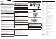
Front
LED
The blue LED light comes on.
On: when powered on, during reboot, during normal use
Off: when [Off] is selected (see "VB-M40 Operation Guide",
"Installation Conditions" in Chapter 4, "Setting Page")
* * When [Off] is selected, the LED light will come on for several seconds when
the camera is powered on and during reboot.
SD card cover
Lens
Horizontal viewing angle 55.4°, 20x optical zoom, AF zoom lens
Camera head
Rear
100BT LAN connector
100Base-TX support
PoE power supply (IEEE802.3af standard-compliant)
Power connection terminal
Audio input terminal (dual LINE IN and MIC IN)
External Device I/O Terminals
Audio output terminal (LINE OUT)
Reset Switch
Turn on the power while pushing this switch using a sharp object.
Continue to push the switch for 5 seconds or more to restore all
factory settings except for the date and time.
Bottom
Fixing screw hole for tripod
Screw holes for ceiling mounting
Used for the ceiling plate with the optional ceiling mount cover or the
ceiling bracket for optional indoor dome housing.
MAC address
The camera's unique address. Write the address on the back of this
Installation Guide before installing the camera.
Safety wire attachment
When installing the camera on a ceiling using the optional ceiling
mount cover or indoor dome housing, attach the safety wire that
comes with the optional product.
Serial No.
The camera's serial number. Write the number on the back of this
Installation Guide before installing the camera.
•
•
Installing the Camera
The following explains the procedures to install the camera on a ceiling using the ceiling mount
cover SS40-S-VB/SS40-B-VB (optional).
Before installing the camera, set the IP address and other network information on the camera
using the "VB Initial Setting Tool".
For details on how to operate the "VB Initial Setting Tool", see "VB-M40 Operation Guide".
1
Determine an installation position for the camera and drill holes in the ceiling
Use the template bundled with the ceiling mount cover (optional) to determine the positions of
the fi xing screw holes and wiring hole according to the camera orientation. Next, drill holes in
the ceiling.
2
Attach the ceiling plate to the camera
Fix the ceiling plate to the camera with the four screws (M3) bundled with the ceiling mount cover
(optional).
3
Secure the safety wire
Securely attach the safety wire to an anchor or structure. After securing one end of the safety
wire to the ceiling, secure the other end to the camera using the screw that is fastened to the
camera.
Important
If a wiring hole cannot be opened in a concrete ceiling, etc., secure the wiring to a comparable location.
4
Fix the ceiling plate to the ceiling
Fix the ceiling plate to the ceiling at four points using the appropriate screws. The ceiling
plate has four diameter Φ 4.5 screw holes. Use the appropriate screws for ceiling mounting in
accordance with the condition and material of the installation site.
5
Connect the LAN cable to the camera through the wiring hole
If an AC adapter PA-V17 (optional) or external power supply is used, connect the power
connector to the camera.
Connect cables to external device I/O terminals and audio input/output terminals as
necessary.
6
Install the ceiling mount cover
Align the (O) mark on the ceiling mount cover with the (I) mark on the rear of the camera, and
turn the cover clockwise to the (I) position.
Check that the ceiling mount cover is securely attached.
Note
Cutout section
If the cables cannot be stored above a ceiling made of concrete, etc., or if
the cables do not fi t within the ceiling mount cover, bend the cutout section
of the ceiling mount cover using diagonal pliers, etc., to create a cutout
through which to guide the cables.
7
Reboot the camera when the installation is complete
The camera position is initiated (see "Maintenance" in Chapter 4, "Setting Page" of the "VB-M40
Operation Guide").
Important
The camera can be installed in the upright position. Attach commercial anti-slip guards to the base of the
camera and set on a fl at, stable surface without inclination, or fi x the camera to a tripod, etc. Be sure to use
a tripod with mounting screws shorter than 5.5 mm (0.22 in). Using a tripod with mounting screws 5.5 mm
(0.22 in) or longer may damage the camera. Also, use a tripod with a base diameter of 30 mm (1.18 in) or
more.
2
4
7
3
Connecting the Camera
Power Connection
Power can be supplied to the camera in the three ways described as follows.
J
PoE (Power over Ethernet)
The camera supports PoE functions. Power can be supplied to the camera by using a LAN cable
to connect it to a PoE HUB that conforms to the IEEE 802.3af standard.
Important
Check with your Canon sales representative for more information about PoE HUB and Midspan
technology.
Some PoE HUBs allow current limits for each port, but applying limits may interfere with performance. If
using this type of PoE HUB, do not limit the operating current.
Some PoE HUBs have total consumption current limits for ports, which can interfere with performance
when multiple ports are in use. For more information, check the instruction guide for your PoE HUB.
Use a category 5 or higher cable 100 m (328 ft.) or less in length for the LAN cable that connects the
camera and the PoE HUB.
When the camera is connected to a switching HUB, changing the connection while the camera is
operating may cause the HUB learning function to interfere with communication. Do not change the
connection when the camera is operating.
The camera can also be connected to an AC adapter (optional) while receiving power from a PoE
HUB. In such cases, the PoE power supply is given priority, and the camera does not use the power
supply from the AC adapter (optional). When the PoE power supply is disconnected, power is supplied
automatically from the AC adapter (optional). Midspan (a LAN cable power supply device) is a device
that, like a PoE HUB, supplies power to the camera via a LAN cable.
•
•
•
•
•
•
J
External Power Supply
12-VDC or 24-VAC input can be used.
Connect the bundled power connector as shown below.
Screwdriver
Tightening torque: 0.2 N·m
(1.77lbf·in) (max)
Strip
Approx. 4 to 6 mm
(0.16 to 0.24 in)
Power connector
(bundled)
For 12-VDC and 24-VAC input, use a power supply insulated
from 100 VAC.
12-VDC can be connected in a non-polar confi guration.
Important
The power supply should be within the following voltage range.
24 VAC: Voltage fl uctuation within 10% of 24 VAC (50 Hz or 60
Hz ± 0.5 Hz or less)
Current supply capacity of at least 1.0 A per camera
12 VDC: Voltage fl uctuation within 10% of 12 VDC
Current supply capacity of at least 1.5 A per camera
When using a 12-VDC battery power supply, be sure to connect
resistors of at least 0.5 - 1.0 Ω/20 W in series to the power line.
For an external power supply, use a double-insulated device.
•
•
•
•
•
Recommended Power Cables for VB-M40 [Reference]
Cable (AWG)
#24 #22 #20 #18 #16
Conductor size (Φ)
(0.52 mm)
(0.020 in)
(0.65 mm)
(0.026 in)
(0.82 mm)
(0.032 in)
(1.03 mm)
(0.041 in)
(1.30 mm)
(0.051 in)
12 VDC maximum cable length
5 m (16.4 ft.) 9 m (29.5 ft.) 14 m (45.9 ft.) 23 m (75.4 ft.) 32 m (105.0 ft.)
24 VAC maximum cable length
11 m (36.1 ft.) 18 m (59.0 ft.) 29 m ( 95.1ft.) 46 m (151.0 ft.) 64 m (210.0 ft.)
Use UL cable (UL-1015 or equivalent) for 12-VDC or 24-VAC wiring.
J
AC Adapter
Use the dedicated PA-V17 AC adapter (optional).
Note
The camera does not have a power switch. Connecting and disconnecting the LAN cable (PoE power
supply), AC adapter, or external power supply plug turns the power ON and OFF, respectively.
When the camera needs to be rebooted, perform the reboot operation from the camera setting page
(see "Maintenance" in Chapter 4, "Setting Page," of the "VB-M40 Operation Guide").
•
•
External Device I/O Terminals
External device I/O terminals consist of two input and output systems each. VB-M40 Viewer and
RM Viewer can be used to check external device input status and control ouput to an external
device (see "Operating the External Device Output" and "Displaying Event Status" in the "VB-M40
Operation Guide").
J
External Device Input Terminals (IN1, IN2)
External device I/O terminals consist of two sets (IN1, IN2) of two terminals, with the negative
terminal connected to the camera interior GND. Connecting cables to the positive and negative
terminals and creating electrical continuity or insulation between the terminals notifi es the viewer.
Important
When connecting sensors and switches, connect terminals that are electrically isolated from the
respective power and GND.
Do not push the external device I/O terminal button with too much force. Doing so may cause the button
to remain pushed-in.
•
•
J
External Device Output Terminals (OUT1, OUT2)
External device output terminals consist of two sets (OUT1, OUT2) of two terminals. The sets
have no polarity. Controls from the viewer can be used to switch between continuity and insulation
between the terminals. Using optical couplers, the output terminals are isolated from the camera's
internal circuit.
+
Internal Connection Diagram
Internal controller
External device
Output terminal
IN1, IN2
Output terminal
OUT1, OUT2
+3.3 V
0.1 µF
10 kΩ 10 kΩ
1 kΩ
External device
The load connected to the output terminals should be within the following rating range.
Rating between output : maximum voltage 50 VDC
terminals Continuous load current at or
below 100 mA
Note
Adaptive wiring for external device cables
Solid conductor AWG: No. 28 - 22
Conductor size: Φ 0.32 - 0.65 mm (0.013 - 0.026 in)
Cable strip should be approx. 8 - 9 mm (0.315 - 0.354 in)
Audio Input/Output Terminals
Each audio input/output terminal has one input system and one output system.
Connecting the camera to an audio input/output device such as a microphone or a speaker with
an amplifi er allows you send/receive audio through the viewer.
J
Audio Input Dual LINE IN/MIC IN (monaural input)
Although the camera has a single audio input system, it supports two types of microphone inputs:
LINE IN and MIC IN. Before using the audio input, change the input mode on the Setting Page
(see "Audio Input Mode" in the "VB-M40 Operation Guide"). LINE IN is selected by default.
Input terminal: Φ 3.5 mm (
Φ 0.14 in) mini jack (monaural)
Dynamic MIC IN
Input impedence: 1.75 kΩ ± 20%
* Supported microphones: Output impedence: 400 Ω to 600 Ω
Condenser MIC IN
Input impedence (microphone bias resistance): 2.2 kΩ ± 20%
Microphone power supply: plug-in power (voltage: 1.8 V)
* Supported microphones: Condenser microphones with plug-in power support
LINE IN
Input level: up to 1 Vp-p
* Use a microphone with an amplifi er.
J
Audio Output Terminal LINE OUT (monaural output)
Connect the camera to a speaker with an amplifi er. Audio can be sent to the speaker from RM
Viewer.
Output terminal: Φ 3.5 mm (
Φ 0.14 in) mini jack (monaural)
Output level: up to 1 Vp-p
* Use a speaker with an amplifi er.
Important
According to microphone specifi cations, switch the LINE IN/MIC IN settings on the Setting Page before
use (see "Audio Input Mode" in the "VB-M40 Operation Guide"). Using a wrong input may damage the
camera and/or microphone. Be sure to confi gure settings correctly.
Microphone characteristics may affect volume and sound quality.
Use RM Viewer to send audio to the speaker. VB-M40 Viewer cannot be used to send audio.
Images and audio do not always synchronize properly.
Audio may be interrupted depending on PC characteristics and network environment.
Images and audio can be distributed to up to 30 clients. However, audio may be interrupted when
distributing to many clients.
Audio may be interrupted when using antivirus software.
Connecting and disconnecting the LAN cable interrupts the audio. Use the viewer to reconnect.
•
•
•
•
•
•
•
•
•
•
•
6
Attaching to a Junction Box
Use the junction box plate (bundled with the
ceiling mount cover (optional)) to mount the
camera to the junction box.
1 Attach the junction box plate to the
junction box with screws that match the
screw holes in the junction box.
2 Mount the ceiling plate to the camera
using the four bundled fi xing screws
(M3).
3 Attach the ceiling plate to the junction
box plate using four bundled fi xing
screws (M3).
4 Turn the ceiling mount cover over the
ceiling plate to fi x it in place.
Using an SD Memory Card
Place your fi ngers on the left and right holds of the SD card cover and pull to remove. To return the
SD card cover to the camera, use the same procedure in reverse.
SD card slot
Inserting the card
Push the SD memory card as far as possible into the SD card slot.
Removing the card
Push the SD memory card in all the way until the card slightly pops out. Pinch the card and
remove.
Important
Make sure the SD memory card isn't write-protected.
When using an SD memory card with the camera for the fi rst time, it is recommended that you format
the card after inserting it into to the camera (see "Memory Cards" in Chapter 4, "Setting Page" in the
"VB-M40 Operation Guide").
Insert the SD memory card before installing the camera.
•
•
•
Junction box plate
Fixing screw
(bundled) x 4
Ceiling Plate
Fixing screw
(bundled) x 4
Fixing screws
M3 × 4
(bundled)