Before Reading the Operation Guide Notice on New Functions and Changes Operation Guide This notice describes new functions and specification change with the latest firmware, and the latest information such as changes to the "Operation Guide" on P. ii to P. xvi. For those already using this product For the latest information of the firmware update, please read P. ii to P. xvi. For those using this product for the first time Please read P. ii to P. xvi in conjunction with P.
Checking and Updating the Firmware Version Use the Camera Management Tool to check and update the firmware version of the camera. Download the latest firmware from the Canon website and update the firmware of the camera, as required. For details on using the Camera Management Tool, please refer to "Camera Management Tool User Manual". Latest Firmware Versions Camera Model Firmware Version VB-H45, VB-H45B*, VB-M44, VB-M44B* VB-H730F Mk II VB-S30D Mk II, VB- S31D Mk II 1.1.
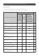
New Functions and Specification Changes Target Models The new functions and specification changes of the new firmware are indicated below. Screenshots on this notice may differ from the actual screens, depending on the model you are using.
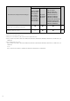
Target Models New Functions and Specification Changes VB-R13VE, VB-R13 VB-R11VE, VB-R11 VB-H45, VB-M44 VB-R12VE, VB-R10VE VB-H730F Mk II VB-M50B, VB-H652LVE VB-S30D Mk II VB-S30VE VB-H651VE, VB-H651V VB-S31D Mk II VB-S800VE VB-M641VE, VB-M641V VB-S800D Mk II VB-S910F VB-M640VE, VB-M640V VB-S900F Mk II VB-H761LVE-H, VB-H761LVE VB-S805D Mk II VB-H760VE, VB-H751LE-H VB-S905F Mk II VB-H751LE, VB-M741LE-H VB-M741LE, VB-M740E Factory Default Settings: Setting values changed (User Authority) P.
Operating Environment The operating environment for the latest firmware is described below. PC Environment Details CPU (Recommended) Intel Core i7-2600 or higher Graphics Board (Recommended) Not specified Memory (Recommended) 2 GB or higher Viewer Display (Recommended) 1920 x 1080 or higher Windows 7 Ultimate/Windows 7 Professional/Windows 7 Internet Explorer 11 32/64-bit, Enterprise/Windows 7 Home Premium SP1 32/64-bit Chrome 65*2 OS and Compatible Web Browser Windows 8.1/Windows 8.
Verified Mobile Devices (Setting Page, Camera Viewer, Mobile Camera Viewer) – As of April 2018 Mobile Devices OS Compatible Web Browser Windows 10 Home 64-bit Internet Explorer 11, Microsoft Edge*1 Surface 3 – Must be configured to allow use of JavaScript, and web storage – For Camera Viewer only, cookies must be enabled iPad Pro 12.9-inch iPad Pro 10.5-inch iPhone 7*2 iPhone 8 Plus*2 iPhone X*2 iOS 10.3.3 iOS 11.3 Nexus 9 Android 7.1.1 Chrome 65*1 Galaxy Tab S 8.4 Android 4.4.
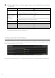
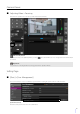
Camera Viewer Adjusting Video > Focusing One-shot AF operations are now also possible in the Camera Viewer. [One-shot AF] button Use when [Focus] is set to [Manual]. When you click to manual. , the camera will focus once using autofocus and then switch Important For precautions on focusing and the focus range, please refer to "Operation Guide". Setting Page [Basic] > [User Management] It is now necessary to enter a confirmation password when setting the password for an authorized user.
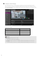
[Camera] > [Initial Settings] Recommended values have been changed for [Exposure], [Shutter Speed Limit (Lower)], [Shutter Speed Limit (Upper)], and [Shutter Speed], which are displayed when [Motion Priority] in [Simple Camera Settings] is selected. The notes regarding [Motion Priority] and [Depth Priority] in [Simple Camera Settings] have been changed according to the improved performance. [Simple Camera Settings] Type Motion Priority [Exposure] Auto [Shutter Speed Limit (Lower)] 1/1000 (sec.
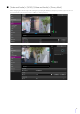
[Video and Audio] > [ADSR] / [Video and Audio] > [Privacy Mask] When changing the camera angle in the settings for specifying the ADSR area and privacy mask area, presets can now be selected from a preset selection box in addition to slider operations.
[Video and Audio] > [On-screen display] The maximum number of characters that can be entered for [Text string display] has been increased to 40 when [Display designated string] is selected in [Text display]. Note • Setting the [Text display], [Date display], and [Time display] to the same position may result in not displaying all of the information. In such case, items set with [Upper right] or [Lower right] for [Position of text display] are prioritized for display.
[Half Duplex] You can prevent howling that occurs when the microphone and speaker are placed nearby. However, there is no sound sent from the camera to the viewer while the camera is receiving audio from the viewer or while an audio file is being played back. Therefore, even if the [Audio Reception] button of the viewer is active (purple), audio input from the microphone cannot be received.
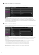
List of Factory Default Settings The setting values for the factory default settings are changed as indicated below.
Information on Other Changes In addition to the changes due to the firmware update, the following changes have also been made to the descriptions in the "Operation Guide". The target models for these changes are indicated below.
Discontinuation of the Setup CD-ROM The setup CD-ROM has no longer been included with the camera. The distribution of files such as the software, user manuals, and License Agreement of Software that were stored on the setup CD-ROM has been changed as indicated below. Type Name Distribution Network Video Recording Software RM-Lite No longer provided Camera Management Tool Software Recorded Video Utility On-screen Display Assist Tool* 1 Download from the Canon website Installer name: VBToolsInstall.
Revision to the Operation Guide Privileges Required for Operating the Camera Viewer The following menu and buttons can be used even if all the privileges of an authorized user or a guest user are disabled. [Main] Menu – [Language] Button – [Switch Users] – [Settings Page] – [Mobile Camera Viewer] [Reconnect] Button Information Display [Video Record] > [Upload] The following "Important" text has been deleted.
Troubleshooting Countermeasures have been added for the following problems. Problem Countermeasures Cannot connect to the camera. Video is not displayed. There is no audio.* The viewer gets disconnected. • Configure to exclude the camera, or the software where the problem occurred, in your security software. The Camera Viewer will not launch. • Use one of the following procedures, when you launch the Camera Viewer and a file block security warning is displayed because of an unverified publisher.
Network Camera Operation Guide / / / / This User Manual should be read before using the network camera.
Introduction Thank you for purchasing a Canon Network Camera (hereafter referred to as the camera)*. The camera is for indoor use only. This “Operation Guide” explains the camera settings and operations. Read this guide carefully before using the camera to ensure correct use. * The cameras described in this manual may include models not available in your country and/or region. For the latest information on this product (firmware and software, user manuals, operating environment, etc.
The product should be installed in such a manner that it is clearly visible to all persons whose images and voices are monitored by the product. In addition, signage prominently displayed in close proximity to the product and clearly visible to all persons monitored by the product should inform such persons that the product records both their images and their conversations.
Security Export Control This product is subject to security export control. Therefore, to export or carry it overseas may require an authorization by governmental agencies.
User Manuals Types of User Manuals The following describes the different camera user manuals. When you are instructed to reference another manual, its name will be listed as shown below. Installation Guide (Included) This describes precautions and procedures for installing the camera. Operation Guide (This Guide) This explains the camera initial settings, camera angle settings, camera viewer operations, settings on the Setting Page, and troubleshooting, etc.
Symbols Used in This Guide Symbols Indicating Camera Models Explanations that differ depending on the camera model are indicated by the camera name and the following symbols. Symbol Camera Model HM4x VB-H45, VB-M44 H730 VB-H730F Mk II S30 VB-S30D Mk II S31 VB-S31D Mk II S80x VB-S800D Mk II, VB-S805D Mk II S90x VB-S900F Mk II, VB-S905F Mk II Symbols Indicating Safety Precautions This section explains the symbols used in this guide.
Safety Precautions This section explains precautions that must be followed when using the camera. If they are not followed, injury, death and/or property damage may occur. Read the following information carefully and be sure to follow the precautions. Important Warnings Caution TO REDUCE THE RISK OF ELECTRIC SHOCK, DO NOT REMOVE COVER (OR BACK). NO USER-SERVICEABLE PARTS INSIDE. REFER SERVICING TO QUALIFIED SERVICE PERSONNEL.
Precautions Camera Precautions Warning If you discover defective conditions such as smoke, strange sounds, heat or strange odors, immediately stop using the camera and contact your nearest dealer. Fire or electric shock may result from continued use. Failure to do the following may result in fire or electric shock. • If thunder starts, stop installation or inspection etc. and do not touch the camera or continue connecting the cable. • Do not disassemble or modify the camera.
Caution Periodically inspect the parts and screws for rust and loosening. For inspections, please contact the dealer where you purchased the product. Failure to follow these precautions could result in injuries and equipment damage due to falling items. Cleaning the Camera Turn off the power before cleaning the camera. Cleaning the Exterior 1 Dampen a soft cloth with water or diluted neutral detergent and gently wipe away any grime. 2 Wipe with a dry cloth.
Table of Contents Introduction...................................................................................................................... 2 Precautions for Use (Disclaimer) ............................................................................................ 2 License Agreement of Software.............................................................................................. 3 Trademarks ................................................................................................
Chapter 3 Setting the Camera Angle Flow for the Setting of the Camera Angle...................................................................... 38 Step 1 Configuring the Camera ............................................................................................ 38 Step 2 Setting Zoom ............................................................................................................. 38 Step 3 Setting the Focus...............................................................................
mDNS.................................................................................................................................... 86 [Basic] > [User Management] Configuring Accounts and Privileges....................................................................... 87 Administrator Account .......................................................................................................... 87 Authorized User Account..............................................................................
Registering a Preset............................................................................................................ 118 [Camera] > [Preset Tour] Setting the Preset Tour Route ................................................................................ 121 Screen Composition............................................................................................................ 121 Tour Route Settings........................................................................................
[Video Record] > [E-mail Notification] Setting E-mail Notification ...................................................................................... 148 E-mail Notification ............................................................................................................... 148 [Event] > [External Device] External Device Input Triggered Operation Settings ............................................. 149 External Device Output .................................................................
[Security] > [SSL/TLS] Setting HTTP Communication Encryption .............................................................. 187 Certificates .......................................................................................................................... 187 Certificate Management...................................................................................................... 188 Encrypted Communications...........................................................................................
List of Viewer Messages.............................................................................................. 223 Messages Shown in the Information Display ...................................................................... 223 Restoring Factory Default Settings .............................................................................. 225 Restoring the Initial Settings from a Web Browser..............................................................
Chapter Before Use This chapter explains the camera functions, software and operating environment. It also describes the flow from preparation and setup through to actual use.
Functions of the Network Camera A network camera not only enables you to operate the camera, but also allows you to record and upload the video, and perform monitoring using the various intelligent functions of the camera. However, the functions that can be used differ depending on the model. For the difference in functions by model, please refer to the table below.
Camera Software Before Use The following software is available for efficiently configuring and operating the camera. 1 Camera Operations and Settings Camera operations are performed using the Camera Viewer/Mobile Camera Viewer. Camera settings are specified from the Setting Page. Camera Viewer (P. 39) /Mobile Camera Viewer Controls the camera, and monitors video and various events.
• Playing and deleting videos • Downloading videos to a computer For details on using the utility and its functions, please refer to “Recorded Video Utility User Manual”. The Recorded Video Utility can be installed from the installer. Installer name: VBToolsInstall.exe RM-Lite This software displays, records and plays back video from up to four cameras via a network. Installer name: RMLiteInstall.
RM-64/RM-25/RM-9 Before Use This software allows network cameras to be used for multipoint surveillance, and for displaying, recording and playing back videos from the camera. The number of cameras that can be registered with RM-64/RM-25/RM-9 varies: 64, 25, or 9 cameras respectively can be registered. By using multiple Storage Servers, you can construct a surveillance system supporting up to 512 cameras.
Operating Environment For the latest information on this product (firmware and software, user manual, operating environment, etc.), please refer to the Canon website.
Mobile Devices OS Compatible Web Browser Windows 10 Home 64-bit Internet Explorer 11, Microsoft Edge*1 1 Before Use Verified Mobile Devices (Setting Page, Camera Viewer, Mobile Camera Viewer) – As of May 2017 Surface 3 – Must be configured to allow use of JavaScript, and web storage – For Camera Viewer only, cookies must be enabled Safari*1 iPad mini 4 iPad Air 2 iPad Pro iPhone SE*2 iPhone 7/iPhone 7 Plus*2 iOS 9.3.5 iOS 10.3.2 Nexus 9 Android 7.1.1 Chrome 58*1 Galaxy Tab S 8.4 Android 4.4.
Steps for Setting Up the Camera Step 1 Preparing to Install the camera Make preparations to use the camera via a network. Install the necessary software “Installing Software” (P. 28) Check/configure the computer and web browser security settings “Checking/Configuring Security Settings” (P. 31) Use the Camera Management Tool to configure initial camera settings. “Configuring Initial Camera Settings” (P. 35) Step 2 Installing the Camera Install the camera to suit the environment it will be used in.
Troubleshooting Before Use Please refer to “Appendix” (P. 205), in case of error messages or problems.
26
Chapter Camera Setup To prepare the camera for use, install the necessary software on the computer, and configuring the initial settings for web browser security and the camera.
Installing Software Install the necessary software. Necessary Software You will need the following software: • Camera Management Tool • Recorded Video Utility • .NET Framework 3.5 SP1/.NET Framework 4.5 (unnecessary if already installed on computer) Note If .NET Framework 3.5 SP1/.NET Framework 4.5 is not installed on the computer, the installer will automatically install the version appropriate for the version of Internet Explorer used on the computer.
3 Select the installation method. 4 Confirm or select the software that will be installed. 2 Camera Setup If you select [Easy Installation], confirm the software that will be installed and click [Next]. If you select [Custom Installation], select the software to be installed and click [Next]. The User License Agreement screen is displayed.
5 Read through the user license agreement and click [Yes] if you accept it. Installation starts. 6 Click [Exit] or [Reboot]. The Camera Management Tool icon and Recorded Video Utility icon will be displayed on the desktop.
Checking/Configuring Security Settings Checking Firewall Settings 2 Camera Setup Camera configuration and operation may be blocked, depending on the security functions of the operating system and web browser. Change or check security settings beforehand. To use the software on computers where Windows Firewall is enabled, you may need to add each software as an application allowed to communicate via the firewall.
3 Click [Change settings] > [Allow another app]. 4 Select the software to use, such as [Camera Management Tool], and click [Add]. Settings When Using Windows Server Adding the Camera IP Address as a Trusted Site When the security level for internet sites and intranet sites is set to [High], it is necessary to add the IP address of the camera to the list of trusted sites. Note Set the camera IP address with the Camera Management Tool. For details, please refer to “Camera Management Tool User Manual”.
2 Click the [Security] tab. 3 Click [Trusted sites] > [Sites]. 2 Camera Setup The [Trusted sites] dialog box is displayed. 4 Enter the IP address of the camera under [Add this website to the zone], then click [Add]. Note • Clear the [Require server verification (https:) for all sites in this zone] checkbox if it is selected. The camera’s IP address will be added to the [Websites] list. • You can add IP addresses for multiple cameras by using a wildcard (*) when entering the IP address.
1 Open [Control Panel] and click [Hardware]. 2 Click [Sound]. The [Audio Service Not Running] dialog box is displayed. 3 Click [Yes]. The [Sound] dialog box is displayed. 4 Click the [Playback] tab to confirm that an audio device has been installed. If no audio device is installed, refer to your computer manual.
Configuring Initial Camera Settings 2 Camera Setup To use a camera, it is necessary to first set the administrator account for the camera, then configure the network settings, and then connect the camera and computer via the network. Use the Camera Management Tool to configure these settings. The Camera Management Tool also enables multiple cameras to be configured at the same time. For information on how to use the Camera Management Tool, please refer to the “Camera Management Tool User Manual”.
36
Chapter Setting the Camera Angle H730 S80x S90x After installing the camera, set the camera angle while checking the video displayed on the Setting Page.
Flow for the Setting of the Camera Angle Adjust the camera angle when installing the camera or after changing the installation location. The camera angle settings are configured by accessing the Setting Page (P. 76). Step 1 Configuring the Camera Set the digital zoom and video flip, which affect the camera angle. [Digital Zoom] (P. 96) in [Camera] > [Camera] > [Camera Control] on the Setting Page. H730 [Video Flip] (P. 98) in [Camera] > [Camera] > [Installation Conditions] on the Setting Page.
Chapter Camera Viewer Use the web browser to access the Viewer in the camera to perform camera operations, view live video, and check the status of events.
Viewing Video with the Camera Viewer You can start the Camera Viewer to switch users and check/configure the status of the camera as well as the video display. Note If you open another window or tab to access the camera while an authenticated web page is displayed, the authentication information of the displayed web page may be discarded. In this case, enter the authentication information again.
4 5 Enter the administrator name and administrator password, and click [OK]. Camera Viewer The authentication screen for the Viewer is displayed. The Camera Viewer is displayed. User Authentication When you use the Viewer and the Setting page, an authentication screen is displayed, and you are prompted to enter a user name and password. If you enter the wrong user name or password, you will not be able to connect to the camera. Enter the correct user name and password and connect to the camera.
Authentication screen for the Setting Page Authentication screen for the Viewer The administrator name and administrator password are set using the Camera Management Tool. Important • Change the administrator password periodically to enhance system security. Do not forget the new password. • Restore factory default settings if you have forgotten the administrator account (P. 225). However, you will become unable to connect to the camera because the administrator account is also initialized.
4 Camera Viewer The [Main] menu will be displayed. 2 Click [Switch Users]. The user authentication window is displayed. 3 Enter a user name and password and click [OK]. The Viewer for the user entered for user authentication is displayed. Camera Viewer Access Restrictions You can set authorized users, which require user authentication, and guest users, which do not require authentication. The functions that each user can use in the Camera Viewer depend on the privileges assigned to the user (P.
Administrator: The user assigned all privileges. Access the Viewer using the administrator name and password registered for the administrator account. The administrator can disable all the privileges of an authorized user or a guest user, and completely prohibit authorized users and guest users from accessing the camera. Authorized user: An authorized user has higher privileges than a guest user. It is necessary to register the user name and password (P. 87).
Camera Viewer Screen The privileges required for operating the Viewer are indicated with the following symbols.
(1) Video Display Area Displays video received from the camera. (2) [Reconnect] Button Reconnects to the camera. Can be operated when the Viewer is not connected to the camera. (3) [Full Screen Mode] Button Video is displayed in full screen mode (P. 52). (4) [Switch Area Zoom/Drag to Move] Button HM4x S30 S31 Switch between Area Zoom and Drag to Move functions for dragging in the video display area (P. 58). (5) [BLC] (Back Light Compensation) Button Turns on/off backlight compensation.
(17) [Main] Menu Switches the language or user, and switches the Setting Page or Mobile Camera Viewer. (A) (B) 4 (C) (D) Camera Viewer (A) [Language] Button Switches the display language. (B) [Switch Users] Use this to log in as an administrator or authorized user (P. 42). (C) [Settings Page] The screen switches to the Setting Page (P. 76). (D) [Mobile Camera Viewer] Switches the connection to the Mobile Camera Viewer.
(19) [Camera Operation] Menu Sets the pan/tilt/zoom, focus, exposure, and day/night switch of the camera. HM4x S30 S31 (K) HM4x S30 S31 (L) HM4x S30 S31 (M) HM4x S30 S31 (N) HM4x H730 S30 (O) (P) (Q) (K) Pan/Tilt HM4x S30 S31 Operate a button to move the angle in the direction of the arrow (P. 60). (L) Pan/Tilt Speed HM4x S30 S31 Select the operating speed for the pan/tilt buttons (P. 60). (M) Zoom HM4x S30 S31 Operate a button to zoom in and zoom out (P. 60).
(20) [Event and Input/Output] Menu Enables you to check the output operations and input status of an external device, the detection status of the intelligent function and the status of linked events. (R) (S) (T) 4 Camera Viewer (U) (V) (R) External Device Output Use external device output (P. 72). (S) External Device Input Displays the status of the external device input signal for each input source (P. 72).
Checking Information Information, such as the frame rate, camera pan/tilt/zoom values and descriptions of each function, is shown in the Information Display. Warning and error messages will also be displayed here if there are problems with camera operations or systems. Information Display For details on the information displayed, please refer to “List of Viewer Messages” (P. 223). Important HM4x When [Camera] > [Camera] > [Camera Control] > [Image Stabilizer] (P.
Changing the Reception Video Size and Display Screen Size You can set the size and format of the video received from the camera and the size of the display screen on the computer. Changing the Reception Video Size/Format and Display Screen Size [Video and Audio] menu and configure the video received from the camera. (1) (2) Camera Viewer Open the 4 (3) (4) (1) Video Size Setting Select the size and format of video received from the camera.
[Video Size Set] Setting Selectable Screen Size 1920 x 1080 / 960 x 540 / 480 x 270* Actual Pixels 480 x 270 960 x 540 1920 x 1080 Fit to Window 1280 x 720 / 640 x 360 / 320 x 180 Actual Pixels 480 x 270 640 x 360 1280 x 720 Fit to Window 1280 x 960 / 640 x 480 / 320 x 240 Actual Pixels 480 x 360 640 x 480 1280 x 960 Fit to Window Remarks [Actual Pixels] displays the video at the size at which it is being captured.
(1) (3) (2) (5) (4) (7) (6) (9) 4 (8) Camera Viewer (1) Menu Area Display Switch Button Switches between displaying and hiding the menu bar. (2) [Reconnect] Button Reconnects to the camera. Can be operated when the Viewer is not connected to the camera. (3) Full Screen Mode Switch Button Returns the video display area to the regular view. (4) [Video and Audio] Menu Configures the video display size and audio transmission/reception of the Viewer.
(I) Day/Night Set a capture mode suited to the brightness of the camera installation environment (P. 61). (J) Switch Area Zoom/Drag to Move HM4x S30 S31 Switch between Area Zoom and Drag to Move functions for dragging in the video display area (P. 58). (K) Pan/Tilt/Zoom If you enable this button (make it purple), the pan/tilt/zoom sliders are displayed on the screen to perform operations.
Operating the Camera This section describes the operations and configuration required for using the camera, such as obtaining camera control privileges, setting the angle and focus. Important It is necessary to obtain the camera control privileges to perform the operations and configuration as first described in this section. To use the camera, you must obtain control privileges with the Viewer.
Important • Multiple users cannot obtain control privileges simultaneously. • The Obtain/Release Camera Control Privileges button is displayed for authorized users and guest users if [Camera Control] is selected in [Basic] > [User Management] > [User Authority] on the Setting Page. • Administrators can take away camera control privileges from authorized users or guest users. Authorized users can also take away camera control privileges from guest users.
Moving Using the Sliders Drag the pan and tilt sliders to pan and tilt the camera. Drag the zoom slider to zoom the camera. The slider can also move by clicking directly on the slider bar. Tilt Slider Move the camera vertically. Camera Viewer Zoom Slider Drag upward to zoom in (telephoto), drag downward to zoom out (wide-angle). 4 Pan Slider Move the camera horizontally. Note H730 S80x S90x Slider operations cannot be performed unless the Viewer PTZ or Digital PTZ is started.
Enhanced Digital Zoom Maximum Telephoto (Temporary Stop Position) Digital Zoom Range Enhanced Digital Zoom Range Optical Zoom Range Using Area Zoom/Drag to Move HM4x S30 S31 You can drag on the video display area to zoom in and out, and change the camera angle. Note You cannot use Area Zoom or Drag to Move when using Viewer PTZ or Digital PTZ. Using Area Zoom to Zoom In and Out 1 Click the [Switch Area Zoom/Drag to Move] button to enter 2 Drag out a frame in the video display area.
Using Drag to Move to Change the Camera Angle 1 Click the [Switch Area Zoom/Drag to Move] button to enter (Drag to Move) mode. 4 Camera Viewer 2 In the video display area, drag in the direction you would like to change the camera angle. An arrow will be displayed. The camera angle will move in the direction of the arrow. The maximum length of the arrow is half the width and height of the video display area, and movement speed increases with the length of the area.
(1) [Pan/Tilt] The camera angle will move in the direction of each arrow. Movement will continue while you hold the button down, and stop when you release it. Click the center button to move the camera angle to the midpoint of the pan/tilt range of motion. However, if a view restriction is set (P. 115) and the midpoint is outside the restrict view area, the camera angle moves to the edge of the restrict view area. (2) Pan/Tilt Speed Set the operation speed by the [Pan/Tilt] button.
Move by Clicking If you click outside the frame, the frame will move and center on that point, panning and tilting the camera. Adjusting Video Open the [Camera Operation] menu to operate focus, exposure compensation and day/night function. Focusing HM4x H730 S30 4 Camera Viewer Focus on the subject. [Auto] HM4x S30 Focusing is performed automatically. [Manual] You can click and hold the (Near) and (Far) buttons to adjust the focus in the near and far directions.
Using Backlight Compensation Click [BLC] to brighten video that is dark due to backlight. The back light compensation button becomes active (purple) while backlight compensation is being performed. Click the button again to cancel backlight compensation. Important • You cannot use the [BLC] button if [Smart Shade Control] is set to [Auto] on the Setting Page. • You cannot use the [BLC] button if [Exposure] is set to [Manual] on the Setting Page.
Viewer PTZ and Digital PTZ Viewer PTZ and Digital PTZ are both functions which allow easy panning, tilting and zooming using the digital zoom. Viewer PTZ Digital PTZ Enlarges the specified part of the video transmitted from the Transmits only the cropped part of the entire area that can camera and then displays it in the viewer. be captured by the camera. The size of the received data is small. Camera control is not required. Camera control is required.
Preview Frame 3 Move the frame to the area you would like to magnify and resize the frame as desired. Move or Resize by Dragging Press the mouse button inside the frame and drag it to move the preview frame. If you press the mouse button and drag outside the frame, a new preview frame will be drawn. You can resize the preview frame by dragging an edge of the frame. Move by Clicking If you click outside the frame, the preview frame will move and center on that point.
Cropping Video With Digital PTZ Panel 1 Click the [Digital PTZ] button. 4 2 Camera Viewer The [Digital PTZ] button changes active (purple), and the Digital PTZ panel is shown in the control display area. In the Digital PTZ panel, move and resize the preview frame. The preview frame operations are the same as with the Viewer PTZ (P. 63). The preview frame size can be set to any of 5 sizes. The screen sizes according to the setting in [Basic] > [Video] > [All Videos] > [Video Size Set] (P.
Using Presets or the Home Position H730 S80x S90x You can use a registered preset or home position to specify the range for Digital PTZ. If you select a preset, the preview frame on the Digital PTZ panel moves to the preset position, and the video inside the frame is shown in the video display area. Note Register presets in advance in [Camera] > [Preset] > [Register Preset] on the Setting Page (P. 118). Exiting Digital PTZ The Digital PTZ exits if you perform one of the following operations.
Saving Snapshots You can take snapshots while checking the video in the video display area. 1 Click the [Snapshot] button at the moment you want to capture a still image. 4 Camera Viewer The snapshot panel is opened in the control display area and the still image from the instant that the button was clicked is displayed. If you click the [Snapshot] button again, the image displayed in the Snapshot panel will be updated. 2 To save the snapshot, right-click on the Snapshot panel.
Recording Video to a Memory Card Manually record video being shown in the video display area to a memory card inserted in the camera. Note • You can manually record video if the following conditions have been met. – The memory card inserted in the camera is mounted. – [Operation Settings] is set to [Save Logs and Videos] in [Memory Card] > [Memory Card Operations] (P. 196) on the Setting Page.
Confirming Recorded Video Use the Recorded Video Utility to confirm and play back the video manually recorded to a memory card. For details, please refer to “Recorded Video Utility User Manual”.
Receiving/Transmitting Audio Open the [Video and Audio] menu to set the audio reception from the camera, the audio transmission from the Viewer and the corresponding volumes. Receiving Audio Receive audio from the microphone connected to the camera and play it back in the Viewer. 1 In the [Video and Audio] menu, click the [Audio Reception] button. Audio reception starts. The [Audio Reception] button icon will change to active (purple) while receiving audio.
3 In [Input Volume], adjust the volume to an appropriate level using the slider. Note • To transmit audio, you must first set [Video and Audio] > [Audio] > [Audio Server] > [Audio Reception from Viewer] to [Enable] on the Setting Page (P. 137). • While the icon is active (purple), audio is constantly transmitted even if you close the [Video and Audio] menu. • If [Audio Communication Method] is set to [Half Duplex] in [Video and Audio] > [Audio] > [General Audio] on the Setting Page (P.
Checking the Status of Event Detection In the [Event and Input/Output] menu, you can operate the output of an external device and check the status of input of the external device, detection of intelligent functions, and occurrence of linked events. HM4x H730 S30 S31 S80x S90x (1) (2) (3) (4) Operating External Device Output You can operate output for the external device set in [Event] > [External Device] (P. 149) on the Setting Page.
(2) [Intelligent Function (Video Detection)] The status of video detection set in [Event] > [Intelligent Function] > [Video Detection] (P. 161) is displayed for each detection setting number. When the detection settings configured in Intelligent Function (Moving Object Detection, Abandoned Object Detection, Removed Object Detection, Camera Tampering Detection, Passing Detection, or Intrusion Detection) are triggered, the corresponding icon will turn green.
74
Chapter Setting Page The Setting Page enables you to configure all the settings required for using the camera. Please configure the settings on the Setting page according to how the camera will be used, before you use the camera. The Setting Page also provides menus for when the camera is in operation; for example, camera maintenance.
How to Use the Setting Page This section explains operations up to displaying the Setting Page, and common Setting Page operations. Note • The Setting Page can only be operated by administrators. • Use the Camera Management Tool in advance to configure the administrator account and network settings. Accessing the Setting Page Directly enter the IP address set in the Camera Management Tool into a web browser to display the Setting Page of the camera.
Important • If you open another window or tab to access the camera while an authenticated web page is displayed, the authentication information of the displayed web page may be discarded. In this case, enter the authentication information again. • To ensure security, exit the web browser after completing settings on the Setting Page and after using the Camera Viewer. • Do not open multiple Setting Pages at one time and try to change the settings of a single camera.
Help Click [Help] at the beginning of any setting item to display a detailed explanation of that setting item. Setting Ranges and Character Limits For settings where you must enter numerical values or characters, the setting range or limits on the number of characters will be displayed. Please enter the settings within the displayed limits.
(2) Pan/Tilt Slider Pan and tilt operations are the same as in the viewer (P. 57). (3) Zoom Slider Zoom operations are the same as in the viewer (P. 57). (4) Panorama Screen/Full-View Screen Displays the full range of motion of the camera. You can set areas, etc. using mouse operations on the panorama screen for some Setting Pages. HM4x S30 S31 If a panorama image is registered in the camera (P. 110), the panorama image is displayed.
About Each Setting Page This section will give an overview of each item in the Settings Menu and each submenu. Each of the [Basic], [Video and Audio], and [Video Record] menus has a [Video] submenu, but the functions are all common. The functions can be set in any of the menus and the settings will be reflected in all of the [Video] submenus. 80 Basic • Network (P. 83) Network settings for connecting to the camera. • User Management (P.
Video and Audio Server • Server (P. 138) Settings for HTTP server, SNMP server, FTP server usage or WS-Security time checks. • Video Server (P. 141) Settings for clients that can be connected to a video server. • Audio Server (P. 136) Settings for audio transmission from the camera to the computer, and audio reception from the computer to the camera. The settings of this item are the same as those in [Video and Audio] > [Audio] > [Audio Server].
Event • External Device (P. 149) Operation settings for external device output and for external device input triggered events. • Audio Detection (P. 152) Detected changes in audio input from the microphone connected to the camera can trigger operations such as video recording or e-mail notification. • Timer (P. 155) The timer function can generate events that can trigger operations, such as video recording and e-mail notifications, at regular intervals. • Intelligent Function (P.
[Basic] > [Network] Configuring Network Settings Network settings for connecting to the camera. 5 Setting Page The following settings can be configured here. • LAN • IPv4 • IPv6 • DNS • mDNS Important If any network settings are changed, the camera may become inaccessible from the active web browser. In this case, a confirmation dialog box will be displayed when you click [Apply] or [Apply and reboot]. Click [OK] to apply the new settings.
Important • Contact your System Administrator for the [IPv4 Address], [Subnet Mask] and [IPv4 Default Gateway Address] if you set the IPv4 address manually. • If any of the [IPv4 Address], [Subnet Mask] or [IPv4 Default Gateway Address] settings are wrong, the camera may become inaccessible via the network. If this occurs, use the Camera Management Tool to reset the address. [IPv4 Address Settings Method Select the method for setting the IPv4 address.
[IPv6 Default Gateway Address] Enter a default gateway address if [Disable] is specified in [Auto (RA)]. Be sure to set this when connecting the camera to a different subnet from that of the Viewer. [IPv6 Address (Auto)] If [Enable] is specified in [IPv6] and [Enable] is specified in [Auto (RA)] and [Auto (DHCPv6)], then the automatically acquired address will be displayed.
mDNS This will configure settings for using multicast DNS. If you use mDNS, the IP address and host name of the camera will be broadcast to other hosts on the network. [Use mDNS] Select this to enable or disable mDNS.
[Basic] > [User Management] Configuring Accounts and Privileges You can change the administrator account, add new authorized users, and set the privileges for authorized users and guest users. For details on user privileges, please refer to “Camera Viewer Access Restrictions” (P. 43). [User Management] is the same as [Security] > [User Management]. Settings configured on one [User Management] page are also reflected on the other. 5 Setting Page The following settings can be configured here.
To delete an authorized user from the list, select the user and click [Delete]. User Authority Set the privileges for authorized users and guest users. This setting enables you to set access restrictions for the Camera Viewer (P. 43). [Privileged Camera Control], [Camera Control], [Video Distribution], [Audio Distribution] Select the items for granting users privileges. An authorized user has higher privileges than a guest user.
[Basic] > [Date and Time] Setting the Date/Time Camera date and time settings. The following settings can be configured here. • Current Date and Time • Settings 5 Setting Page Current Date and Time The date and time set in the camera are displayed. Settings Set the date and time setting method, time zone and daylight saving time for the camera. [Settings Method] Select the date and time setting method. [Set manually] Set the desired date and time in [Date] and [Time].
[Last Sync Time] The time last synchronized with the specified NTP server will be displayed. [Synchronize with computer time] The date and time will be synchronized with that of the computer currently accessing the camera. After clicking [Apply], [Settings Method] will change to [Set manually]. [Time Zone] is not automatically selected, so set it if necessary.
[Basic] > [Video] Setting Video Size and Quality General video settings, such as the size and quality of JPEG and H.264 video transmitted from the camera. [Video] is common with [Video] found in [Video and Audio] and [Video Record]. A setting configured in any of the [Video] submenus will be reflected in the other [Video] submenus as well. 5 Setting Page The following settings can be configured here. • All Videos • JPEG • H.264(1) • H.
Important Changing the [Video Size Set] selection and clicking [Apply and reboot] will disconnect all connections and then change all the video sizes. Consequently, users connected to the camera must reconnect. If the [Video Size Set] selection is changed, review the following settings and check the operation. – ADSR (P. 127) – Privacy Mask (P. 131) – Intelligent Function (P. 157) – Preset (P. 118) – View Restriction (P.
Important • When [H.264(1)] or [H.264(2)] video is used for memory card recording and upload, the following restrictions apply to the setting. – [Bit Rate Control]: [Use bit rate control (constant bit rate)] only – [Target Bit Rate (kbps)]: [3072] or less – [I Frame Interval (sec)]: either [0.5], [1], or [1.5] • When dual streaming H.264 videos, setting the video size for H.264(1) and H.264(2) to the following combinations restricts the frame rate to a maximum of 15 fps.
[Basic] > [Viewer] Configuring the Viewer Configure the startup, authorization, and view of the Viewer. The following settings can be configured here. • General • Viewer Settings General [Default Page] Sets the Setting Page or the Viewer as the first page to display when the camera is connected. If users other than the administrator use the Viewer, set [Default Page] to [Display Viewer].
[H.264 for Guest Users] Set whether guest users may receive H.264 video. If you select [Enable], the [H.264] button will be displayed even when a guest user connects to the viewer (P. 47). If you select [Enable], the [CANON SOFTWARE LICENSE AGREEMENT] dialog box is displayed. Click [Yes] to accept the terms of the license agreement. Important Additional H.264 licenses are required to receive H.264 video on multiple computers (P. 20).
[Camera] > [Camera] Setting General Camera Controls Settings for the camera name and external input/output devices, and for camera use and installation settings. The following settings can be configured here. • Camera Name • Camera Control • Day/Night (when Auto is set) • Installation Conditions • Camera Position Control • External Input Device 1, 2 • External Output Device 1, 2 Camera Name Set the camera name. [Camera Name] Enter any camera name. Be sure to enter a name in [Camera Name].
[Maximum Digital Zoom Magnification] HM4x Sets the maximum zoom magnification for digital zoom. [Image Stabilizer] HM4x Select this to enable or disable blur reduction in video due to camera vibration. If there is still blur after selecting [On1], select [On2]. The angle of view will be narrower and video noisier when using the Image Stabilizer, compared to when it is not used. Important HM4x • The image stabilizer is not effective when the subject is shaking.
Installation Conditions Configure settings for camera use suitable for the location the camera will be installed. [Dome] HM4x Select whether a dome is used. To use the camera with a separately sold indoor dome housing for the camera, select [Enable]. [LED Setting] Select whether to turn on the LED indicating the camera operation status. If you select [Turn On], the LED will light up when turning the power on, rebooting, and during normal use.
[Camera] > [Initial Settings] Setting Initial Video Settings Sets initial settings, such as video quality compensation, at camera start up. If you change settings, the changes are immediately reflected in the video display area and Viewer, even if you do not click [Apply]. A message confirms whether you want to display the current camera status as the initial settings if the current camera status differs from the settings registered as the initial settings when you access [Initial Settings].
S30 S31 If you select [Do Not Register], the camera angle will move to the home position the next time it is booted. If you have not specified the home position, the camera angle will move to the factory default setting. For information on specifying the home position, please refer to P. 118. Note HM4x S30 S31 When [Digital PTZ Position] is set to [Do Not Register], you can perform pan, tilt, and zoom operations on the video display area using Area Zoom (P. 58).
Important Note the following regarding [Simple Camera Settings]. [Motion Priority] – Flickering may occur due to fluorescent lighting, etc. – In low-light conditions, video may become comparatively darker than [Standard Settings], and noise may increase. [Depth Priority] HM4x H730 – In low-light conditions, video may become comparatively darker than [Standard Settings], and noise may increase. [Low Light Visibility] – Residual images may appear for moving subjects in dark situations.
• It is recommended that you check that the camera is focused whenever you reboot the camera. • The estimated focus ranges depending on the [Day/Night] setting are shown in the following table. Focus [Installation Conditions] > [Dome] Auto/Manual HM4x [Disable] Day/Night Settings Day Mode Max. Wide-Angle Night Mode Max. Telephoto Max. Wide-Angle Max. Telephoto 0.3 m (12 in.) – infinity 1.0 m (3.3 ft.) – infinity 1.0 m (3.3 ft.) – infinity 1.5 m (4.9 ft.) – infinity [Enable] 2.0 m (6.6 ft.
[Shutter Speed Limit (Lower)] If [Exposure] is set to [Auto], [Auto (Flickerless)], [Auto (Flickerless2)] ( S30 AE)] ( HM4x H730 ), a minimum shutter speed can be selected. S31 S80x S90x ), or [Auto (Aperture-priority [Shutter Speed Limit (Upper)] If [Exposure] is set to [Auto], [Auto (Flickerless)], or [Auto (Aperture-priority AE)] ( HM4x H730 ), a maximum shutter speed can be selected. [Shutter Speed] If [Exposure] is set to [Auto (Shutter-priority AE)] or [Manual], you can fix the shutter speed.
This enables stable exposure to be obtained even in environments with large differences in light and dark on the screen. Use this to stabilize the exposure for scenes when cars are passing or people are entering and exiting. [Spot] Performs photometry with the center of the screen. This enables the appropriate exposure to be obtained for subjects in the center of the screen, regardless of differences in light and dark around the screen.
[Sodium Lamp] (approx. 2,000K) Select this when capturing under an orange sodium lamp. [Halogen Lamp] (approx. 2,700K - 3,200K) Select this when capturing under a halogen lamp or incandescent lamp. [One-shot WB] If you set white balance to [Manual], this will force the white balance to match the light source and lock the setting. Setting Method Example: Illuminate a white subject (white paper, etc.) using the light source, making sure the subject fills the entire screen, and then click [Exec].
[Auto] The camera automatically determines ambient brightness and switches to Day Mode or Night Mode. [Day Mode] Captures normal color video. [Night Mode] Video turns to monochrome. Removes the infrared filter to increase sensitivity. HM4x H730 Important • If you use [Auto], conduct a thorough operation test beforehand to check the effectiveness of the setting.
[Camera] > [Day/Night Mode Focus] Day/Night Mode Focus HM4x H730 Set the focus position when switching day/night. It is necessary to change the focus position since the wavelengths of regular lighting such as fluorescent lamps and infrared lighting differ. The following settings can be configured here.
[Fluorescent] Select this option to capture video under fluorescent, LED, sodium or mercury lighting. [Halogen Lamp] Select this option to capture video under halogen or incandescent lighting. [Infrared Light (740nm)] Select this option to capture video under infrared (740 nm wavelength) illumination. [Infrared Light (850nm)] Select this option to capture video under infrared (850 nm wavelength) illumination.
[Night Mode] Video turns to monochrome. Removes the infrared filter to increase sensitivity.
[Camera] > [Panorama] Creating a Panorama Image HM4x S30 S31 You can create a panorama image that captures the entire area that can be captured by the camera. Created panorama images are displayed in the Viewer and part of the Setting Page. The following settings can be configured here.
2 Set the panorama creation area using the video display area. Operate the camera angle to get the positioning value in the video display area, and specify the panorama creation range. 5 Setting Page [Upper Limit]/[Lower Limit]/[Left Limit]/[Right Limit] Operate the camera angle to the upper limit, lower limit, left limit, and right limit to set in the video display area. Click [Get value] in each position to reflect the values to the panorama creation range frame.
Capturing starts, and the panorama image is created. Click [Cancel] to cancel capturing. To recapture part of the image: A lattice frame is displayed on the created panorama image. Right-click with the mouse pointer over the area to recapture and select [Recapture] to recapture that area only. To capture the entire panorama image again: Click [Exec] of [Start] again. 5 In [Finish], click [Exec]. The created image is not yet saved in the camera. 6 Click [Apply].
The image file is saved in the specified location. Opening the Image File 1 In [Load from file], click [Exec]. 2 In the displayed dialog box, select the image file to use and click [Open]. The panorama image is displayed. Capture Settings [Exposure Lock] The exposure for the selected position will be automatically adjusted and locked during capture.
[Camera] > [View restriction] Setting View Restriction HM4x S30 S31 Set the range that the camera can capture. You can use this, for example, to limit zoom or the angle of view to a certain range when publishing live video. The following settings can be configured here. • View restriction View restriction Recording outside the view restriction is not possible. Scope of View Restriction Settings Restrictions set by the view restriction function are applied in the following cases.
Configuring View Restrictions Set a restrict view area and click [Apply] to restrict the capture range of the Camera Viewer. Important • If you have changed how the camera is installed, reconfigure the view restriction settings. • Check view restrictions again if you change the [Basic] > [Video] > [All Videos] > [Video Size Set] settings on the Setting Page.
View Restriction Operation Knob (Telephoto) View Restriction Operation Knob (Wide-angle) Drag the frames displayed on the panorama screen to set the restrict view area. (1) (2) (3) (4) (1) Pan/Tilt Preview Frame (Red Frame) Displays the vertical and horizontal range the camera can move. You can directly change the restrict view area by dragging the pan/tilt preview frame.
Tilt Control Range Maximum Vertical Capture Range Maximum Wide-angle Viewing Angle Pan Control Range Maximum Horizontal Capture Range • The pan and tilt ranges vary depending on the zoom ratio (view angle). When using wide-angle, the camera operating angle would allow capture outside the view restrictions if the angle remained the same. Therefore, it is narrowed automatically. Restricted view angle 5 Setting Page Setting view restrictions automatically restricts the camera operating angle.
[Camera] > [Preset] Registering Presets By registering settings as presets, such as camera angles and camera settings (e.g. exposure), the presets can be easily called up by Viewers to apply the settings. The following settings can be configured here. • Camera Settings • Register Preset Important • It is strongly recommended you register as presets, the positions Intelligent Function will use for the camera.
• Maximum 21 presets (including the home position) H730 S80x S90x 1 Operate the panorama image to set the angle you want to register as the preset. The camera angle can also be operated from the following screens. HM4x S30 S31 Video Display Area Panorama Screen Preview Frame 5 Setting Page H730 S80x S90x Video Display Area Full-View Screen Preview Frame 2 Click [Camera Settings] to set the items as necessary. Set the items to apply in the preset.
[Preset Name] Enter a preset name. Be sure to enter a preset name in [Preset Name]. [Show in Viewers] Select [Enable] to allow the Camera Viewers to use the preset. 4 Click [Add]. Note HM4x S30 S31 If the preset position is outside the restrict view area, 5 To register multiple presets, repeat steps 1 – 4. 6 Click [Apply]. (a warning icon) is displayed on the left. The preset is saved in the camera. Note Click [Clear] to discard the settings and restore the settings saved in the camera.
[Camera] > [Preset Tour] Setting the Preset Tour Route HM4x H730 S80x S90x You can have the camera automatically tour multiple registered presets to allow monitoring. The following settings can be configured here. • Route List • Edit Tour Route 5 Setting Page Important HM4x Intelligent Function cannot be used while using preset tour. Note • Preset tour is not performed while the camera control privileges are obtained in the Camera Viewer or the video is displayed on the Setting Page.
HM4x (1) (2) (4) (3) (5) H730 S80x S90x (2) (4) (3) (6) (1) [Route List] HM4x The list of preset tour routes. Displays the tour conditions that are set. Up to five tour routes can be set. (2) Tour Condition Settings Set the conditions for touring (P. 123). (3) [Edit Tour Route] Displays a list of the presets to tour. The presets are toured from the top of the list. You can change the order of the presets and set the time to stop at the preset positions, etc.
(a) (b) (c) (a) Pan/Tilt Preview Frame (Red Frame) Displays the vertical and horizontal range the camera can move. Displayed when the restricted view is set (P. 114). (b) Preview Frame (Blue Frame) Indicates the current trim position in the video display area. (c) (6) Digital PTZ Panel H730 S80x S90x Displays the full video obtained by the camera when starting [Preset Tour]. Setting Page Preset Preview Frame (White Frame) Indicates the preset/home position that is currently selected.
[Always] Preset tour is always performed. Note When [Disable] is selected, the following preset tour route settings cannot be configured. [Route Name] HM4x Enter the tour route name. [Specify Active Time] Select [Specified] to configure a preset tour at a predetermined time, and enter the start time and end time for the preset tour. If [Viewers Connected] is set for [Conditions to Enable Settings], the preset tour operates when the Viewer is connected to the camera at the tour start time.
Note If a preset has already been added to [Edit Tour Route] when another preset is added from [Preset List], the added preset will be displayed below the preset selected in [Edit Tour Route]. 6 Configure the preset speed and pause duration. Select the preset to configure in [Edit Tour Route] and set the tour operation. [Speed (PT)] HM4x Select the camera pan/tilt speed for moving to the next preset. [Pause (sec)] Enter the time the camera pauses at the preset position.
[Video and Audio] > [ADSR] Reducing Data Size by Lowering Video Quality in Specific Areas Reduces the size of transmitted H.264 video by reducing the video quality of non-target areas, such as ceilings and the sky. ADSR is an abbreviation for Area-specific Data Size Reduction. The following settings can be configured here. • Specified Area • ADSR Important Some image scenes and settings for selected areas may not be able to reduce data size using ADSR.
Important • If you change the [Video Flip] setting in [Camera] > [Installation Conditions], review the specified area settings. • Reconfigure the specified area if you change the [Video] > [All Videos] > [Video Size Set] settings. HM4x S30 S31 • Configure the specified area to a slightly larger size. • Specified areas may deviate slightly from the specified position depending on the zoom position.
[Enable in H.264(1)] Select [Enable] to lower video quality of outside areas set with [Specified Area] in H.264(1) video. [Enable in H.264(2)] Select [Enable] to lower video quality of outside areas set with [Specified Area] in H.264(2) video. [Data Size Reduction Level] Set the data size reduction level for the outside area of [Specified Area]. If you select [Low], the data size reduction effect is lower. If you select [High], the data size reduction effect is higher.
[Video and Audio] > [On-screen display] Displaying Date, Time and Text on the Video Displays the date and time, camera name and other text on the Video. The following settings can be configured here. • Date display • Time display • Text display • Common Settings 5 Setting Page Important The on-screen time display is not suitable for usage where high reliability is required. Only use it as reference information on systems where utmost and constant reliability is required for surveillance.
Text display [Text display] Select the text strings to display on the Video. [Display designated string] Displays the text string entered in [Text string display] below. [Display camera name] Displays the camera name entered in [Camera Name] (P. 96). [Position of text display] Select position for text display on the Video. [Text string display] If [Text display] is set to [Display designated string], enter the text string to be displayed in alphanumeric characters.
[Video and Audio] > [Privacy Mask] Setting Privacy Mask Mask any areas of the camera video. You can check the camera video and set up to eight privacy masks. When the camera is panned, tilted, or zoomed, the privacy mask areas follow the camera video. HM4x S30 S31 The following settings can be configured here.
HM4x S30 2 S31 In [Add mask area], click [Add]. The preview frame attached with the area number is shown on the video display area. The privacy mask area for the corresponding number is also displayed on the privacy mask registration area. Privacy Mask Registration Area Preview Frame Privacy Mask Area Area Number 3 Set the size and position for the preview frame in the video display area. Drag the preview frame shown in the video display area to the position you want to mask.
7 Click [Apply]. The privacy mask area is saved to the camera. Saved privacy mask areas are shown in the video display area and the privacy mask registration area. Important • Check privacy mask settings again if you change the [Basic] > [Video] > [All Videos] > [Video Size Set] settings. • You will need to set the position of the privacy mask again if you change the [Video Flip] setting in [Camera] > [Camera] > [Installation Conditions].
1 Select the privacy mask area you want to change. 2 Change the position and size of the privacy mask area. Move the preview frame by dragging it and change its size by dragging the handles () positioned on its four sides. Note To discard changes and restore settings saved to the camera, click [Clear]. However, note that mask area settings that have not been saved in the camera by clicking [Apply] are all discarded. 3 Click [Apply]. The changed privacy mask area is saved to the camera.
[Video and Audio] > [Audio] Setting Audio Input/Output Settings for audio input from the microphone connected to the camera and audio output from the Viewer. The output sound clip used when an event is triggered can also be registered. [Audio Server] is the same as [Server] > [Audio Server]. Settings configured on one [Audio Server] page are also reflected on the other. 5 Setting Page The following settings can be configured here.
[Input Volume] Set the input volume from the microphone connected to the camera when [Audio Input] is set to [Enable]. This is applied when [Audio Server] > [Audio Transmission from the Camera] (P. 136) is set to [Enable]. [Current Volume Level] When [Audio Input] is set to [Enable], the current volume level is displayed on the status bar. [Output Volume] HM4x H730 Enter the output volume from the Viewer to the speaker connected to the camera.
When set to [Enable], audio data transmission will pause while there is no sound input from the camera. This can reduce the load on the network used. [Audio Reception from Viewer] HM4x H730 Select to receive audio from Camera Viewer and RM Viewer. Received audio can be output from a speaker with an amplifier connected to the camera. Network 5 HM4x H730 You can upload up to three sound clips for playback when an event is triggered.
[Server] > [Server] HTTP, SNMP and FTP Server Settings Settings for HTTP server, SNMP server, FTP server usage or WS-Security time checks. The following settings can be configured here. • HTTP Server • SNMP Server • SNMP v1 and v2c Server • SNMP v3 Server • FTP Server • WS-Security HTTP Server Set the authentication method and HTTP port number.
[Use SNMP v3] If you select [Enable], you can use SNMP v3 to browse the camera information from an SNMP manager. [Administrator Contact Information] Enter contact information (e-mail address, etc.) for the administrator of the camera. Setting information can be referenced by the SNMP manager. [Administration Function Name] Enter the camera name used for administration. Setting information can be referenced by the SNMP manager. If left blank, the camera model name will be used.
WS-Security [Check Time on Authentication] Select whether to check the time information of data transmitted by the client.
[Server] > [Video Server] Video Transmission Settings Settings for clients that can connect to a video server. The following settings can be configured here. • Video Server 5 [Maximum Number of Clients] Enter the maximum number of clients that can be connected to the camera at the same time. If set to [0], only administrators will be able to connect.
[Server] > [RTP Server] RTP Settings Set the video and audio transmission using RTP. The following settings can be configured here. • RTP Server • Audio Multicast • RTP Stream 1 to 5 RTP Server Enable RTP, and set the RTSP authentication method and port number. [RTP] Select this to enable or disable RTP. [RTSP Authentication Method] Select an authentication method for RTSP.
RTP Stream 1 to 5 You can set each stream for RTP stream transmission in an RTP Stream 1 to RTP Stream 5 session. [Video Size] Select the video format (JPEG or H.264) and video size for the RTP stream. The video sizes for JPEG will vary depending on the [Video Size Set] settings (P. 91). The video sizes for H.264 will be determined according to the [H.264(1)] and [H.264(2)] settings in [Video] (P. 92). In addition, [H.264(2)] cannot be set for multiple RTP streams.
[Video Record] > [Upload] HTTP and FTP Upload Settings Settings for uploading video via HTTP or FTP when an event is triggered. Use [Server] > [Server] (P. 138) to configure HTTP server and FTP server settings for uploading. The following settings can be configured here. • Video Record Settings • General Upload • HTTP Upload • FTP Upload Important • When using the upload function or recording to a memory card, the following settings are required according to each event.
[Video Format] Select the video format for upload. Video size and quality of the uploaded video follow the settings in [Video] (P. 91). Important • For H.264(1) or H.264(2), the following settings must be configured in [Video] > [H.264(1)] (P. 92) or [H.264(2)] (P. 93). – [Bit Rate Control]: [Use bit rate control (constant bit rate)] – [Target Bit Rate (kbps)]: [3072] or less – [I Frame Interval (sec)]: [0.5], [1] or [1.5] • You cannot select a different H.
[Proxy Port] If using a proxy server, enter the port number of the proxy server. [Proxy User Name], [Proxy Password] Enter to use a user name and password for the proxy server. Digest authentication is not supported. [Parameter (query string)] Enter the request parameters. Parameters can be specified using the “%” character (P. 206). [HTTP Upload Test] Clicking [Exec] initiates an upload test based on the settings currently entered.
[Subdirectory Name to Create], [File Name to Create] If [File Naming] is set to [User Settings], enter the subdirectory name to be created as well as the name of the created file. Parameters can be specified in the entry with the “%” character (P. 206). [FTP Upload Test] Clicking [Exec] initiates an upload test based on the settings currently entered. Only a single JPEG will be uploaded, but it is not necessary to click [Apply] at that time. After entering a password, first click [Exec], then click [Apply].
[Video Record] > [E-mail Notification] Setting E-mail Notification Settings for sending an e-mail notification to a specified recipient when an event is triggered. The following settings can be configured here. • E-mail Notification E-mail Notification Set the mail server to be used for e-mail notifications and the content of the e-mail to be sent. [Notification] [Subject] and [Message Body] are text.
[Event] > [External Device] External Device Input Triggered Operation Settings Operation settings for external device output and for external device input triggered events. The following settings can be configured here. • External Device Output 1, 2 • External Device Input • External Device Input 1, 2 5 Setting Page External Device Output Set the operation for output to the external device. The camera has two external device outputs. You can set the output for each of them.
Important When [Active Output Format] is set to [Pulse] and a timer is used (P. 155), contact output is controlled only once when the timer starts. External Device Input [External Device Input Event] Select whether to use the input from an external device, such as a connected sensor, as an event. External Device Input 1, 2 (Title Is Displayed for HM4x H730 Only) You can set the operation to be performed when an event is triggered by input from an external device.
[External Device Output for Active Event] Select the actions of external device output when an active event is triggered. [External Device Output for Inactive Event] Select the actions of external device output when an inactive event is triggered. [Audio Playback at Active Event] HM4x H730 If you select [Enable], the sound clip specified in [Sound Clip] will play back at active events for the external device input.
[Event] > [Audio Detection] Abnormal Audio Input Triggered Operation Settings Audio input from the microphone connected to the camera, such as loud noises or screams, or when expected audio input ceases, can trigger operations such as video recording or e-mail notification. The following settings can be configured here. • Volume Detection • Scream Detection Important For notes on use of audio detection, please refer to “Precautions for Built-In Camera Functions and Software” (P. 8) in “Safety Precautions”.
[ON Event Operation] If [Enable] is set, [Preset] ( HM4x S30 S31 ), [Video Record] and [E-mail Notification] will be executed according to their settings when a volume detection event is triggered (ON event). [OFF Event Operation] If [Enable] is set, [Preset] ( HM4x S30 S31 ), [Video Record] and [E-mail Notification] will be executed according to their settings when a volume detection event is completed (OFF event). [Ongoing ON Event Operation] Select the operation to be performed during an ON event.
It is necessary to set presets beforehand with [Camera] > [Preset] (P. 118). Important HM4x S30 S31 When the camera is triggered by a scream detection event and moved to a preset position specified in the [Preset] settings, camera control privileges are released, even if the user has obtained those camera control privileges using the Camera Viewer or other camera control applications. [Video Record] Select whether to record video depending on the scream detection event.
[Event] > [Timer] Timer Triggered Operation Settings The timer function can generate events that can trigger operations, such as video recording and e-mail notifications, at regular intervals. You can set the following two types of timers. • 24 hours continuous from specified time • Within specified time only Either type can be set to trigger timer events at regular intervals. Setting Page The following settings can be configured here.
If you select [Enable] and a timer event is triggered, video will be transmitted to the recording destination specified in [Video Record] > [Upload] > [Video Record Action] (P. 144). [E-mail Notification] When [24-Hour Continuous Settings] is set to [Disable], select whether to send an e-mail notification depending on the timer event. If [Enable] is selected, e-mail notification is performed when a timer event is triggered. To use e-mail notification, you must set [Video Record] > [E-mail Notification] (P.
[Event] > [Intelligent Function] - Overview Intelligent Function The Intelligent Function records video, sends e-mail notifications, plays audio and starts other operations when it detects changes in the video due to subject movement. The Intelligent Function has the following modes.
Video Detection Detects changes to video in a specified area. There are six types of detection to suit your needs. Moving Object Detection Detects moving objects. This function can be used to detect visitors or suspicious individuals. Moving object detection is triggered while moving objects are inside the detection area. Moving object enters/leaves area Detected Detection begins when a moving object enters the designated area.
Camera Tampering Detection Detect when capture is being disrupted. This can be used to detect when the camera orientation is changed or the video display is obscured with spray, etc. Camera tampering detection is triggered when an area exceeding a specified ratio of change is continuously altered. Detected Tampering 5 Background Video Generated Setting Page Detection begins when the ratio of change in a video exceeds a specified amount.
Audio Detection Detects audio input to the camera. There are two types of detection. These are set with [Event] > [Audio Detection] (P. 152), not with [Intelligent Function]. [Volume Detection]: Detects when volume level exceeds or falls below a reference volume. [Scream Detection]: Detects screams or cries from people. Notes on Intelligent Function Settings and Operations • When setting the Intelligent Function, do an actual detection test to confirm that detection will be performed correctly.
[Event] > [Intelligent Function] - Video Detection In video detection, select the type to detect, and set the detection area for video changes while checking images on the camera. You should also set which operations (e-mail notification, record video, outputting to an external device) should be carried out when changes are detected. 5 Setting Page The following settings can be configured here.
2 Click [Add] in [Detection Settings]. 3 Select [Detection Settings Number] (1 to 15) and [Detection Type] for the detection setting to be added. Note You can register up to 15 detection settings. 4 Click [OK]. The detection settings added to [Detection Settings] are displayed and [Enable these detection settings] is selected. Note • To disable the detection settings, clear the [Enable these detection settings] checkbox. • Enter the [Detection Settings Name] if necessary (P. 166).
5 Configure the detection criteria. Set criteria in the video display area or [Detection Conditions] tab (P. 165). The detection criteria differ according to the detection type. 5 Configure event settings. Set which operations to carry out for video detection in the [Event] tab (P. 178). 7 To register multiple detection settings, repeat steps 2 to 6. 8 Click [Apply]. Setting Page 6 The settings are saved to the camera. Note To restore settings, click [Clear] before applying.
Important • The non-detection area set in the non-detection area settings is reflected in all detection settings. • If the area in the detection settings and the area in the non-detection area settings overlap, the non-detection settings are prioritized. 1 Click [Non-Detection Settings] to display the list of non-detection area settings. 2 Click [Add]. The non-detection area settings added in [Non-Detection Settings] are displayed and the [Enable non-detection area] checkbox is selected.
3 Set a non-detection area in the video display area. Click the mouse to create a polygon. For information on the creation method, please refer to “Using [Polygonal]” (P. 166). 5 • Click [Clear Area] to set the non-detection area again. Setting Page Note • You can create a polygonal area with a maximum of 32 vertices. You cannot set a non-detection area with only a straight line. • Enter [Non-detection Area Name (within 64 half-width alphanumeric characters)] as necessary.
Settings Common to Each Detection Type (1) (2) (3) (1) [Detection Settings Name (within 64 half-width alphanumeric characters)] Enter a detection name. Be sure to enter a name in [Detection Settings Name (within 64 half-width alphanumeric characters)]. (2) [Area Shape] Configure whether the detection area is a rectangle or a free-shape polygon. Note You cannot select [Area Shape] for camera tampering detection.
[Clear Area] The detection area configured with [Polygonal] is deleted. (3) [Display Color] Select the color for detection areas and detection lines. How to Configure Moving Object Detection Set the area you want to detect a moving object in as a detection area. 5 Setting Page 1 Select [Rectangular] or [Polygonal]. 2 In the video display area, draw the area in which you would like to detect moving objects (P. 166).
Note If an object is placed in or removed from the moving object detection area, “detected” status will be triggered for Moving Object Detection. How to Configure Abandoned Object Detection Set the area you want to detect an abandoned object in as a detection area. 1 Select [Rectangular] or [Polygonal]. 2 In the video display area, draw the area in which you would like to detect abandoned objects (P. 166). 3 Configure the size of the object needed for detection in [Object Size (%)].
Profile lines of detected abandoned object How to Configure Removed Object Detection – Specifying the profile lines of objects for removal detection If you cannot detect the intended objects using one of these methods, use the other method. 5 Setting Page Set an area around the target objects, for Removed Object Detection. The following methods are available for configuring removed object detection.
4 Configure [Duration (Sec)] for time required for an object to be detected as a removed object. 5 Click [Apply]. Important • A removed object may not be detected in the following cases.
Click [Restart intelligent function] again. Important Set detection areas so that they precisely match the profile lines of the target object. Influence from the target object’s shadow or adjacent objects may result in the target object being recognized as larger than it actually is and may not trigger removed object detection. If this occurs, reconfigure the detection area to outline the recognized target object. 4 Follow steps 4–5 in “Setting a Broad Area for Detecting Removed Objects” (P. 170).
Change Ratio indicator Detection Status for Camera Tampering Detection Moving objects detected are displayed with profile lines. If an object is smaller than [Change Ratio (%)], its profile lines are white. If the obscured area in the video exceeds [Change Ratio (%)], profile lines take on the same color as the detection area, indicating that the camera has “detected” tampering.
Detection line ▼ To configure a polygonal detection line, click the vertices of the line in order. Setting Page Detection line 5 You can configure a polygonal detection line with a maximum of 32 vertices. ▼ Click any of the set vertices. The detection line is determined. Note • Even after configuring a detection line, you can drag each vertex to change the shape of the detection line and the lines between vertices to move the entire detection line. • Click [Clear Line] to delete a detection line.
Object Size Indicator Note A ratio of up to 30% can be set in [Object Size (%)] for passing detection. Detection Status for Passing Detection All moving objects detected are displayed with white profile lines. When the [Decision Point] of a moving object that meets the [Object Size (%)] setting crosses a detection line in the direction specified in [Passing Direction], the profile line changes to the same color as the detection line, and the status becomes “detected”.
Detection Frame Decision point (bottom center) 4 Configure the size of the moving object needed to trigger detection in [Object Size (%)]. Set the size ratio of moving objects for the entire screen. When the setting values or slider is changed, an indicator representing the object size is shown for one second in the center of the video display area allowing you to check the size ratio while specifying the setting.
No.1: Video Detection Status is ON No.2 and 3: Video Detection Status is OFF Displaying Settings for Detection Areas/Detection Lines, Non-Detection Area and Detection Results (Display Options) Configure the detection area/line, non-detection area, and detection results displayed in the video display area. You can select the following for either [Detection Area/Line] or [Detection Results].
2 Select [Reduce effects of lighting change] checkbox. 3 Click [Save settings]. The settings are saved and the Intelligent Function restarts. • Settings in [Reduce effects of lighting change] may not work depending on the operating environment. Repeated sudden changes in brightness may also have the same effect. Perform a detection test to check whether settings work correctly. Setting Page Important • It takes several seconds for the Intelligent Function to restart.
[Event] > [Intelligent Function] - Shared Operations This explains functions common to video detection. Configuring Operations for “Detected” ([Event] Tab) Set operations to be performed upon detection of changes in a subject. (1) (2) (3) HM4x H730 (4) HM4x H730 (5) (1) Specify Operation Timing (Multiple Selections Possible) [ON Event Operation] When selected, the operations set in (2) are performed when the mode becomes “detected”.
[Volume] Set the volume for the sound clip. (5) External Device Output Operations [External Device Output for ON Event] Select this to start or pause output to an external device when the mode becomes “detected”, and to select the operation (active or inactive). [External Device Output for OFF Event] Select this to start or pause output to an external device when “detected” mode ends, and to select the operation (active or inactive).
[Event] > [Switch Day/Night] Executing Presets When Switching Day/Night Mode When events trigger the switching of Day/Night Mode, presets registered in advance can be executed, such as changing the camera angle or video quality settings. The following settings can be configured here. • Day/Night Mode Switching Day/Night Mode Switching [Preset when Switching to Day Mode] Executes the preset when switched to Day Mode. [Preset when Switching to Night Mode] Executes the preset when switched to Night Mode.
[Event] > [Linked Event] Using Event Combinations By linking two types of events, a single event is triggered. Select AND/OR for the event linking method. You can set the operations to perform, such as recording video or sending e-mail notifications, when a linked event is triggered. The following settings can be configured here. • Linked Event 1 to 4 • Event 1, 2 • Operation 5 Setting Page Note You can check the linked event status on the [Event and Input/Output] menu of the Camera Viewer (P. 73).
[Volume Detection]/[Scream Detection] Select whether an ON event or OFF event triggers a linked event in [Volume Detection Status]/[Scream Detection Status]. [External Device Input] Select External Device Input in [External Device Input], and then select an active event or inactive event to trigger a linked event in [External Device Input Status]. [Timer] Select the timer event number to use in [Timer]. [Intelligent Function] Select the Intelligent Function detection setting number (P.
Note HM4x H730 [Audio Playback at ON Event] and [Audio Playback at OFF Event] can only be set when [External Device Input] and [Intelligent Function] is selected as [Event Type] in [Event 1] and [Event 2]. [Sound Clip] HM4x H730 Select the sound clip when [Audio Playback at ON Event] or [Audio Playback at OFF Event] has been set to [Enable]. You must upload the sound clip 1 to 3 with [Video and Audio] > [Audio] (P. 137) beforehand. [Volume] HM4x H730 Enter the volume for the sound clip.
When Events Occur in Order 2-> 1 -> 2 ON OFF ON OFF Event 1 Event 2 ON OFF Consolidated State Both events are ON, but their order of occurrence is incorrect. Therefore, a linked event does not occur here. Event 2 Triggered but Event Gap Setting ([4] sec.) Exceeded Event Gap (4 Sec. in This Example) ON OFF ON OFF Event 1 Event 2 ON OFF Consolidated State The gap between the occurrence of event 2 after the occurrence of event 1 exceeds the value specified for the [Event Gap] setting.
[Security] > [Host Access Restrictions] Setting Access Restrictions Separate access control from IPv4 and IPv6 addresses can be set. The following settings can be configured here. • IPv4 Host Access Restrictions • IPv6 Host Access Restrictions 5 Setting Page Important • To prohibit access via a proxy server in HTTP connection, a proxy server address must be set.
IPv6 Host Access Restrictions Specify the hosts from which IPv6 access is permitted and prohibited. [Apply Host Access Restrictions] Select whether to use IPv6 host access restrictions. [Default Policy] Select whether to allow or block access from IPv6 addresses that have not been specified in [Prefix / Prefix Length]. [Prefix / Prefix Length] Enter IPv6 addresses (prefixes) into the list and select [Yes] or [No] for access for each address.
[Security] > [SSL/TLS] Setting HTTP Communication Encryption Certificate creation and management, and encrypted communication settings. The following settings can be configured here. • Certificates • Certificate Management • Encrypted Communications 5 Setting Page Certificates Create an SSL/TLS certificate. Important Use a self-signed certificate when complete security does not need to be ensured, such as through operation tests.
Certificate Management Manage the SSL/TLS certificate. [Generate Certificate Signing Request] Click [Exec] to create a server private key and generate a certificate signing request. Once processed, the certificate signing request will be displayed in a separate window. Note Generating a certificate signing request takes time, so it is recommended that you stop video transmission and upload processes. [Display Certificate Signing Request] Click [Exec] to view the details of the certificate signing request.
If you select [HTTPS], HTTP access is also redirected to HTTPS to perform SSL/TLS communication. Important • Even if you set SSL/TLS communication here, SSL/TLS communication is not performed unless you install a certificate. • Video distribution performance decreases when performing SSL/TLS communication. If you set [HTTPS], you cannot connect with the RM. Note • It may take a few minutes to generate an SSL/TLS key.
[Security] > [802.1X] Network Port Authentication Settings Settings for 802.1X authentication and authentication status display, and for certificate management. The following settings can be configured here. • 802.1X Authentication • Authentication Method • Certificate Information • Certificate Management 802.1X Authentication Display the 802.1X authentication enable/disable control and status. [802.1X Authentication] Select this to enable or disable 802.1X authentication.
[Client Private Key Status] If no client private key is installed, [Not Installed] is displayed. If a client private key is installed, [Installed] is displayed. This is displayed only when [Authentication Method] is set to [EAP-TLS]. Certificate Management This is displayed only when [Authentication Method] is set to [EAP-TLS], [EAP-TTLS], or [EAP-PEAP].
[Security] > [IPsec] Setting IPsec Settings for using IPsec. The following settings can be configured here. • IPsec • Auto Key Exchange Settings • IPsec Set 1 to 5 Important • To run this camera with IPsec, the communicating devices and network must be set beforehand. Contact your system administrator for these settings. • When connecting with IPsec, set the camera IP address manually. For IPv4 addresses, use addresses with [IPv4 Address Settings Method] set to [Manual] in [Basic] > [Network] > [IPv4].
Auto Key Exchange Settings [IPsec SA Encryption Algorithm] Select the IPsec SA encryption algorithm. The specified algorithm will be checked for an applicable encryption algorithm starting from the left. [IPsec SA Authentication Algorithm] Select the IPsec SA authentication algorithm. The specified algorithm will be checked for an applicable authentication algorithm starting from the left. [IPsec SA Validity Period (min)] Enter the duration of validity for IPsec SA.
[IKE Pre-Shared Key] Enter the pre-shared key for IKE (auto key exchange). Manual [IPsec Set] Select which IPsec sets the camera will use; IPv4, IPv6, or neither. [IPsec Mode] Select the IPsec mode. [Destination IPv4 Address], [Destination IPv6 Address] Enter the IP address of the connection destination. [Source IPv4 Address], [Source IPv6 Address] Enter the IP address of the source. [IPsec Protocol] Select the IPsec protocol. If you select [ESP], enter only the setting items relating to ESP.
Since this setting is used as an ID for identifying the SA, be careful not to specify an inbound SPI whose value is already used in another ESP’s SPI. If the Setting in [IPsec Protocol] Includes “AH” [SA AH Authentication Algorithm] Set the AH authentication algorithm to suit the authentication algorithm supported by the device to connect to. [SA AH Authentication Key (outbound)] Enter the SA authentication key for outbound.
[Memory Card] Memory Card Operations and Information Display Settings for recording video to a memory card inserted in the camera. You can also see the status of the memory card. [Memory Card] is the same as [Video Record] > [Memory Card]. Settings configured on one [Memory Card] page are also reflected on the other. The following settings can be configured here.
Important Be sure to perform the unmount process when turning off the power to the camera or removing the memory card. Failing to unmount first may result in management file problems or the memory card becoming inaccessible. You can use the Camera Management Tool to batch mount/unmount memory cards from multiple cameras. The memory card will be automatically mounted when you insert it into the memory card slot.
If you select [Disable], use the Recorded Video Utility to delete unnecessary videos. For information on the procedure, please refer to “Recorded Video Utility User Manual.” [Auto Video Delete] Select to automatically delete video from the memory card that has exceeded the [Days Saved] setting. If you select [Enable], set [Days Saved] and [Delete Time]. [Days Saved] Enter the number of days for which video recorded to the memory card should be saved.
[Maintenance] > [General] Displaying Camera Device Information and Perform Maintenance Check camera information, such as the firmware version, and perform maintenance on the camera system. The following settings can be configured here. • Device Information • Tool • Initialization 5 Setting Page Device Information [Model Name], [Firmware Version], [Serial Number], [Build Number] and [MAC Address] Displays information about the camera. Tool You can configure/reboot the camera and display licenses.
• • • • • Host Access Restrictions Time Zone Certificates Private Key IPsec If you set this to [Do not save], the above settings are also initialized. Since the administrator account is also initialized, you will become unable to connect to the camera. Use the Camera Management Tool to configure the initial settings. [Restore Default Settings] The initial settings are restored according to the selection in [Network Settings] after rebooting.
[Maintenance] > [Backup / Restore] Saving/Restoring Camera Settings You can save/restore all the camera settings. The following settings can be configured here. • Backup / Restore 5 Setting Page Backup / Restore Configure the settings regarding backup and restoring. Caution You must not turn off the camera while [Back Up Settings] or [Restore Settings] are in operation. Turning off the camera at this stage may result in disabling its ability to boot correctly.
[Maintenance] > [Update Firmware] Updating the Camera Firmware You can update the firmware. The following settings can be configured here. • Update Firmware Device Information [Model Name] and [Firmware Version] Displays the information about the connected camera. Update Firmware Configure the settings related to firmware updates. Caution You must not turn off the camera while it is performing the [Update Firmware] operation.
[Maintenance] > [Log] Checking/Sending Camera Log Information You can check the camera operations and connection history, and set log message e-mail transmission. The following settings can be configured here. • View Logs • Log Notifications 5 Setting Page View Logs Display a history of camera operations and connections. [View Logs] If you click [View], the log messages saved since the camera was started are displayed. For details on log messages, please refer to “List of Log Messages” (P. 211).
[User Name], [Password], [POP Server] Enter the user name and password needed for authentication, and the POP server host name or IP address when e-mail authentication is set to [POP before SMTP]. Enter the user name and password needed for authentication when e-mail authentication is set to [SMTP-AUTH]. [Subject] Enter the subject of the e-mail in alphanumeric characters. [Log Notification Test] Clicking [Exec] initiates an e-mail notification test based on the settings currently entered.
Chapter Appendix This chapter provides supplementary information on camera functions, and explains the measures to take when trouble occurs or a message is displayed during camera use. It also explains how to reset the camera to the factory default setting state.
Modifiers According to the setting item, you can specify parameters using modifier “% characters”.
Available Modifiers The modifiers that can be used for each setting item are specified below. [HTTP Upload] (P. 145) [Parameter (query string)] All modifiers can be used. [FTP Upload] (P. 146) [Subdirectory Name to Create] Only the modifiers %y, %m, %d, %w, %H, %h, %n can be used. [File Name to Create] Only the modifiers %y, %m, %d, %w, %H, %M, %S, %s, %n can be used. [E-mail Notification] (P. 148) [Message Body] All modifiers can be used.
Troubleshooting Before contacting the dealer from whom you purchased the product or Canon Customer Service Center, check the following items. If a log message is displayed, check the details of the message and the corresponding countermeasures in the log message list. Note • For information on troubleshooting for the Camera Management Tool, Recorded Video Utility, and Mobile Camera Viewer, please refer to each individual manual. • A problem caused by the security software may occur.
Problem Countermeasures • The number of Viewers that can access the camera at the same time is restricted by the setting in [Maximum Number of Clients] in [Server] > [Video Server] (a maximum of 30 can be specified). If this restriction is exceeded, a message is shown and video is not displayed. • Video can only be displayed by authorized users and guest users if [Video Distribution] privileges are assigned.
210 Problem Countermeasures Video cannot be recorded on a memory card. • Check [Memory Card] > [Memory Card Information] on the Setting Page (P. 198). • Video cannot be recorded if the memory card has insufficient space and [Memory Card] > [Memory Card Operations] > [Overwrite videos] is set to [Disable] on the Setting Page (P. 197). Set [Overwrite videos] to [Enable] or use the Recorded Video Utility to delete unnecessary videos.
List of Log Messages Log Messages on the Camera The list of log messages displayed in [View Logs] in [Maintenance] > [Log] > [View Logs] on the Setting Page (P. 203). Log messages are classified into the following types.
S311 Working error in external input/output service [err] S411 External input/output service initialization error [crit] Description cannot work extio [%1][%2][%3] (S311) Description extio initialization error [%1][%2] (S411) %1 Error number %1 Error number %2 Cause of error %2 Cause of error %3 Error information Meaning Meaning An error occurred while the external input/output device service was running. An error occurred in the initialization of the external input/output device service.
Audio server error V320 Internal error in intelligent service [err] Description cannot work intelligent [%1][%2][%3]. (V320) %1 Error number %2 Cause of error B301 Audio device error [err] Description cannot use audio device for %1[%2:%3] (B301) %1 Send/Receive type (rx | tx) %3 Error information %2 Error type (open | write | flush) Meaning %3 Error number An internal error occurred in intelligent service.
V402 Video input frozen [crit] Uploader error Description video %1 stalled (V402) %1 Video number Meaning The video input function was stopped because video generation stopped. Description uploader initialization failure - %1 (A470) Countermeasure If the problem persists after rebooting, the camera is faulty. Arrange for servicing. %1 Error number Meaning The uploader could not be initialized. Countermeasure If the problem persists after rebooting, the camera is faulty.
M400 Failed to initialize a memory card [crit] Description Fail SD card initialization(%1).(M400) %1 Card initialization NG (det), power supplies control NG (proc) Meaning R303 Metadata distribution initialization failure [err] Description metadata initialization error (R303) Meaning Metadata distribution initialization has failed. Process to initialize a memory card failed.
H144 Password specification error [notice] Description %1 (http_auth.c.XXX) password doesn’t match for %1 username%2, IP:%3 (H144) URL XSS vulnerability countermeasure implementation (process equivalent to ftpd) %2 User Name %3 IP address Meaning A wrong password was specified in user authentication.
B202 Event receive failure [warning] Description cannot recv event [%1] (B202) %1 Error number Meaning Failed to receive event. B203 Audio message send failure [warning] Video warning V200 Video input warning [warning] Description video %1 warning - %2 (V200) %1 Video number %2 Error number Description audio message send error %1 [%2] (B203) Meaning An error that permits recovery of the video input system was detected.
A135 Invalid upload setting (FTP PORT/ PASV mode) [notice] Description ftp port/pasv mode invalid. uploader set forcibly (A135) Meaning The PORT/PASV mode setting in connection with FTP upload is invalid. The PASV mode was forcibly set. A136 Invalid upload setting (HTTP notification only/image mode) [notice] Description http notice/image mode invalid. uploader set forcibly (A136) Meaning The notification only/image mode setting in connection with HTTP upload is invalid.
ONVIF warning (RTP) R101 RTP session timeout [notice] Description session timeout: session ID=%1 (R101) %1 Session ID Meaning RTP session has timed out. R103 RTSP authentication failure [notice] Description RTSP authorization error (R103) Meaning RTSP authentication has failed. R107 RTSP connection failure [notice] RTSP Error: error_code=%d: Service Unavailable (R107) %d 400: Value used for RTSP is invalid. 401: RTSP authentication failure or missing valid authentication information.
S017 qtimer service started or shut down [info] W040 Clearing to external memory [info] Description %1 the image storing - %2 (W040) Description %1 qtimer (S017) %1 Starting or stopping %1 (starting) or (stopping) %2 Reason for starting/stopping Meaning The qtimer service was started or shut down. Meaning Started or stopped clearing stream recording to external memory. S070 Change to certificate [info] Description %1: succeeded to %2 certificate (S070) %1 ssl or 802.
Video notification V001 Starting and stopping of video server [info] A042 Number of uploads (HTTP) [info] Description uploader http: normal=%1 test=%2 (A042) %1 Number of normal uploads. Description %1 video (V001) %2 Number of test uploads. %1 Starting or stopping Meaning Shows the number of uploads executed. Meaning The video server was started/stopped. V020 Starting intelligent service [info] Description starting intelligent. (V020) Meaning Intelligent service was started.
ONVIF notification (RTP) R005 Starting multicast [info] Description start multicast: profile=%1, num_of_sessions=%2(V=%3, A=%4, M=%5,BC=%6) (R005) %1 Client IP address %2 Profile name of requested MulticastStreaming START %3 Total distribution count of Video stream %4 Total distribution count of Audio stream %5 Total distribution count of Metadata stream %6 Total distribution count of AudioBackChannel Meaning Multicast was started.
List of Viewer Messages Messages Shown in the Information Display Messages shown in the information display of the Camera Viewer are classified into the following three types. Icon Category Explanation Displays help messages related to various buttons, pull-down lists, etc., as well as frame rate and other information. Warning Message Displays a message urging caution to the user when camera control privileges cannot be obtained, the audio session stops, etc.
Message 224 Explanation Cannot be controlled, because it is set to fixed at infinity mode. HM4x H730 S30 You tried to operate the focus when [Focus] was set to [Fixed at infinity]. Cannot be controlled, because it is set to manual mode. You tried to operate the Back Light Compensation button or exposure compensation when [Exposure] was set to [Manual], or [Smart Shade Control] was set to [Auto]. You do not have video reception permission.
Restoring Factory Default Settings If you have forgotten the settings and want to set the camera from the beginning, restore the factory default settings first. It is recommended that you use [Maintenance] > [Backup / Restore] on the Setting Page to create a backup file before restoring the factory default settings (P. 201). Important If you restore default settings, you will become unable to connect to the camera because the administrator account is also initialized.
H730 S30 S31 S80x Reset Switch LED LED S90x Reset Switch Reset Switch LED 226
List of Factory Default Settings Item Item Setting Setting • Settings • LAN LAN Interface Auto Maximum Packet Size 1500 Settings Method Set NTP Server Settings Automatically Set manually Disable • IPv4 NTP Server IPv4 Address Settings Method Auto (DHCP) IPv4 Address 192.168.100.1 Synchronization Interval (minutes) Subnet Mask 255.255.255.
Item Setting Item Setting S31 VB-M44/VB-S805D Mk II/VB-S905F Mk II VB-S31D Mk II • All Videos Video Size Set S80x 1280 x 720 / 640 x 360 / 320 x 180 VB-S800D Mk II/ VB-S805D Mk II • JPEG S90x VB-S900F Mk II/ VB-S905F Mk II Video Quality: 320x180 6 Video Quality: 640x360 6 Video Quality: 1280x720 6 Video Quality: Digital PTZ 6 Video Size: video Transmission 1280 x 720 Maximum Frame Rate: Video Transmission 15.
Item Pan/Tilt/Zoom position HM4x S30 Setting Register S31 Digital PTZ Position Item Pan/Tilt/Zoom position HM4x S30 Do Not Register Setting Register S31 Digital PTZ Position Register H730 S80x S90x • Camera Settings Camera Settings Register HM4x H730 S30 Auto HM4x S30 Manual H730 Exposure Auto AGC Limit 6 Shutter Speed Limit (Lower) 1/30 Shutter Speed Limit (Upper) 1/16000 Shutter Speed 1/1000 Aperture HM4x H730 11 Gain 9 Exposure Compensation 0 Metering Mode Center-Weighte
Item Setting Item Setting S31 Text string display VB-S31D Mk II Common Settings Color of text White Background color Black Color depth of text and background Fill text and background color • Mask area Area S80x VB-S800D Mk II/ VB-S805D Mk II S90x VB-S900F Mk II/ VB-S905F Mk II Installation Location Enable Security Level • All privacy masks Color Black • General Audio MD5 Encryption Algorithm DES • SNMP v1 and v2c Server Disable Input Volume 50 Output Volume HM4x H730 50 Echo Ca
Item Setting Item Multicast Port 0 • HTTP Upload Multicast TTL 1 Notification Audio Transmission Disable Notification Only with HTTP URI • RTP Stream 2 Video Size 480 x 270 JPEG* Frame Rate 10 Multicast Address 0.0.0.0 Multicast Port 0 Multicast TTL 1 Audio Transmission Disable User Name Proxy Server Proxy Port Parameter (query string) • FTP Upload 480 x 270 JPEG* FTP Server Frame Rate 15 User Name Multicast Address 0.0.0.
Item Setting • External Device Input Setting OFF Event Operation Disable External Device Input Event Enable Ongoing ON Event Operation Disable Operation Mode Normally Open Preset HM4x S30 None Active Event Operation Disable Video Record Disable Inactive Event Operation Disable E-mail Notification Disable Ongoing Active Event Operation Disable Disable Preset HM4x S30 None External Device Output for ON Event External Device Output for OFF Event Disable S31 Video Record Disable
Item Setting Item Setting 24-Hour Continuous Settings Disable Start Time 00:00 End Time 00:00 Event Type Intelligent Function Repeat Interval None Intelligent Function Setting 1 Intelligent Function Status ON • Operation Start Time Preset HM4x S30 None S31 Video Record Disable E-mail Notification Disable External Device Output Disable • Timer 4 Disable 24-Hour Continuous Settings Disable Start Time 00:00 End Time 00:00 Repeat Interval None • Operation Event 2 Operation
Item Setting External Device Output for ON Event Disable External Device Output for OFF Event Disable Audio Playback at ON Event Disable Disable HM4x H730 Sound Clip HM4x H730 Volume HM4x H730 50 • Linked Event 3 Event 1 Event Type External Device Input External Device Input Input 1 External Device Input Status Active Event 2 Event Type Intelligent Function Intelligent Function Setting 1 Intelligent Function Status ON Operation Linked Event Disable Event Linking Method AND Event
Item Setting 16: / 32 Yes Authentication Status 17: / 32 Yes • Authentication Method 18: / 32 Yes Authentication Method 19: / 32 Yes User Name 20: / 32 Yes • IPv6 Host Access Restrictions Apply Host Access Restrictions Item Stop EAP-MD5 • IPsec IPsec Disable Setting Auto Key Exchange • Auto Key Exchange Settings Authorize Access IPsec SA Encryption Algorithm AES->3DES Prefix / Prefix Length 01: / 128 Yes IPsec SA Authentication Algorithm HMAC_SHA1_96 02: / 128 Yes IPsec SA Validity
Item Setting SA AH Authentication Key (inbound) Destination Prefix Length • IPsec Set 2 IPsec Set Disable IPsec Mode Tunnel Mode AES SA ESP Authentication Algorithm HMAC_SHA1_96 SA ESP Encryption Key (outbound) SA ESP Authentication Key (outbound) Destination IPv6 Address SA ESP SPI (outbound) Source IPv4 Address SA ESP Encryption Key (inbound) Source IPv6 Address SA ESP Authentication Key (inbound) ESP SA ESP SPI (inbound) Security Gateway IPv4 Address SA AH Authentication Algorithm S
Item Setting Item Setting SA AH SPI (outbound) Overwrite videos Enable SA AH Authentication Key (inbound) Auto Video Delete Disable Days Saved 30 Delete Time 00:00 SA AH SPI (inbound) • IPsec Set 5 • Initialization IPsec Set Disable IPsec Mode Tunnel Mode Destination IPv4 Address Save • Backup / Restore Save Destination Destination IPv6 Address Memory Card • Update Firmware Source IPv4 Address Restore Default Settings Source IPv6 Address Do Not Restore • Log Notifications ESP
Index Numerics Access Restrictions ........................................... 43 Camera Operation Day/Night ..................................................... 61 Exposure Compensation ............................. 61 Focus ........................................................... 61 Pan/Tilt ......................................................... 60 Pan/Tilt Speed ............................................. 60 Zoom ............................................................ 60 Zoom Speed ......
E Easy Installation ................................................. 29 Echo Canceller ................................................. 136 E-mail Notification 148, 150, 153, 154, 156, 178, 182 Encrypted Communications ............................. 188 HTTP Upload .................................................... 145 HTTPS Connection Policy ................................ 188 HTTPS Port ....................................................... 138 I Enhanced Digital Zoom .............................
Maximum Connection Time ............................. 141 Password ..................................................... 41, 87 Maximum Digital Zoom Magnification ................ 97 Post-event Buffer ...................................... 145, 197 Maximum Frame Rate ........................................ 92 Pre-event Buffer ....................................... 145, 197 Maximum Number of Clients ............................ 141 Prefix ..........................................................
Subnet Mask ...................................................... 84 Switching an Authorized User ............................ 42 T Viewer Camera Viewer ...................................... 19, 39 Mobile Camera Viewer ............................ 5, 19 RM-Lite Viewer ............................................. 20 Viewer Message ............................................... 223 Target Bit Rate ................................................... 92 Viewer PTZ .......................................
BIE-7197-000 © CANON INC.