Pixagent ITP Version 2.
Contents Copyright . . . . . . . . . . . . . . . . . . . . . . . . . . . . . . . . Introduction . . . . . . . . . . . . . . . . . . . . . . . . . . . . . . . I Getting Started iv v 1 1 Installing this Software 1.1 System Requirements . . . . . . . . . . . . . . . . . . . . . . . 1.2 Installation . . . . . . . . . . . . . . . . . . . . . . . . . . . . 1.3 Camera Setup . . . . . . . . . . . . . . . . . . . . . . . . . . . 2 2 2 4 II 5 Server Administration 2 Basic Administration 2.1 Control Centre .
4.4 4.5 4.6 Analysis Modes . . . . . . . . . . . . . . . . . . . . . . . . . . 25 Slideshow . . . . . . . . . . . . . . . . . . . . . . . . . . . . . 27 Actions . . . . . . . . . . . . . . . . . . . . . . . . . . . . . . 31 5 Using Actions 5.1 Saving in Place . . . . . . . . . . . . 5.2 Creating a Photoshop Droplet . . . . 5.3 ITP Actions and Photoshop Droplets 5.4 Other Software . . . . . . . . . . . . IV . . . . . . . . . . . . . . . . . . . . . . . . . . . . . . . . . . . . . . . . . . . .
D Adapter Management D.1 Virtual IP Address . . . . . . . . . . . . . . . . . . . . . . . . D.2 DHCP Server . . . . . . . . . . . . . . . . . . . . . . . . . . . D.3 Advanced Settings . . . . . . . . . . . . . . . . . . . . . . . . 68 68 69 70 E Variables 72 E.1 Preset Home Directories . . . . . . . . . . . . . . . . . . . . . 72 E.2 Available Variables . . . . . . . . . . . . . . . . . . . . . . . .
Copyright c °Copyright 2005 Thomas Sapiano. All rights reserved. This document is protected by Canadian copyright law and may not be reproduced without the explicit consent of its author. This document is provided on an as-is basis without warranty - by using this document the reader accepts all responsibility for their actions. The author does not accept any responsibility for problems that may occur while following these directions. r °Photoshop is a registered trademark of Adobe Systems Incorporated.
Introduction Thank you for downloading ITP version 2.0! ITP is a powerful workflow solution for digital photographers and provides a wide variety of features to help you to get your work done faster. In addition to this functionality, ITP 2.0 is also much easier to set up than any product before it - allowing users of all levels to be up and running in no time. This manual provides detailed instructions on the administration and use of this extensive package, for both Standard and Professional editions.
Part I Getting Started 1
Chapter 1 Installing this Software 1.1 System Requirements This software can be run on any machine running Windows 98 or later with the Microsoft .NET Framework installed. To be functional, the machine will need an available network adapter that can accept incoming connections. If you meet those requirements, the program will only need approximately 5MB of free space for the program files as well as sufficient room to store received files.
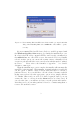
Figure 1.1: Users running Windows XP Service Pack 2 will be prompted with this dialog when installing ITP. Select unblock to allow ITP to operate correctly. If you are running Windows XP Service Pack 2, you will be prompted with the Windows Security Alert message box during the installation process. In order for the FTP server contained in ITP to run correctly, you must select the unblock button to allow ITP access to the network.
1.3 Camera Setup If you plan on using a wireless image transmitter, ITP offers an assisted configuration system to help with that setup process. To do this, double click on the ITP tray icon to launch the Control Centre. When the window is open, enter your wireless network settings into the blue section - the remainder of the settings should be automatically filled in by the system. Once complete, click the appropriate configure...
Part II Server Administration 5
Chapter 2 Basic Administration 2.1 Control Centre In addition to setting up the camera, the control centre provides access to the most commonly accessed administrative functions of this server in a simplified manner. The control centre is designed to be a central repository of the most commonly used functions available in ITP - the dialog is laid out in a visual manner to make it easier to understand, and the available settings are simplified to make them easier to work with.
Figure 2.1: The control centre allows users to quickly access the core functions of ITP, including the ability to configure wireless image transmitters. • The red section covers the core settings for ITP server and allows reconfiguration of the main settings you may wish to manipulate. These features include: – The Adapter field allows you to select the network adapter that you would like to use for receiving images.
– The Add User link allows you to quickly create a new user with default options. This dialog does not have access to the advanced features (see section 3.1 for details), but allows you to quickly add new users to the system. – The Storage Location link provides the ability to reconfigure the location where image files are going to be placed. The home folder of each user is placed inside of this location, so it provides you with the ability to tell ITP where to place all received images.
• The blue section specifies the wireless network settings that will be used by the transmitter. It is important to note that these settings are not automatically retrieved and must be manually specified by the user. For more detailed discussion about wireless settings, please see Appendix B. – The SSID field allows you to specify the name of the network the camera is connecting to. The computer must be set to connect to the same network for the two to communicate.
– The Review Images link launches the live image review system, allowing you to look through received images as well as to see a live preview of images as they are received. See section 4.3 for more information. The above options cover the features that are commonly used by most users so it is generally possible to do all core administration tasks without leaving this dialog.
Chapter 3 Advanced Administration 3.1 Edit Users User profiles are used by ITP to allow cameras to authenticate themselves to the server and prevent other parties from being able to access the server. The edit user profiles dialog can be accessed by right clicking on the ITP tray icon and selecting the ’Edit Users...’ entry. Once open, it allows you to edit existing users and create new ones as desired.
Figure 3.1: The edit users dialog allows administrators to control detailed settings for the user accounts in ITP. • The options section offers a number of simple options with on/off functionality: – When create paths is checked, ITP is able to dynamically create directories as they are needed - when combined with variables, this allows sophisticated directory trees to be generated on the fly.
to be provided to connected clients - this doesn’t effect cameras, however it can help when users are manually connecting to the server. • The Prefix section allows you to enable a simple renaming mechanism to replace the first four characters of image file names. In addition to static strings, this field also accepts the variables used above so it can be used to add specific information directly to the filename.
Figure 3.2: The configure cameras dialog allows you to automatically create configuration files for a number of wireless image transmitters.
• The profile list allows you to select any configuration files that you have already created on this system. If you would like to create a new one, simply select ’Create New...’ and then enter the desired settings in the right pane. To edit an existing profile, simply select it and its settings will be loaded into the dialog for editing. • The send to card button will send the currently selected profile to a memory card loaded in the computer.
• The wireless adapter list allows you to select the network adapter that you would like ITP to extract network settings from. The other fields will automatically be filled in by ITP using this adapter’s setup so make sure to select the correct one. The remaining fields control the parameters that will be placed in the configuration file and uploaded to the camera. As noted above, please hover your mouse over these controls to get detailed descriptions of what they mean.
Figure 3.3: The configure adapters dialog allows you to control which adapter(s) ITP will automatically configure for usage with a wireless transmitter. This selection effects a number of aspects of ITP’s setup, including the addition of virtual IP Addresses to simplify setup. 3.4 Configuration The configure server dialog allows you access to a number of advanced features that do not fit into the categories covered above.
Figure 3.4: The configure server dialog allows access to a number of advanced parameters that control how the server behaves on this computer.
• Allow anonymous logins specifies whether ITP will allow people to log into the FTP server anonymously. This reduces security as users don’t need login credentials to upload photos, however it can simplify setup of cameras using their internal setup mechanisms. • The equivalence threshold field determines how much of the image file is compared when determining whether a new image can overwrite older pictures of the same name.
Part III Professional Edition 20
Chapter 4 Additional Features 4.1 Introduction The professional edition of ITP 2.0 contains a number of powerful features that are not present in the standard edition. To gain access to these features you either need to purchase a licence or activate the free 30-day demo. This chapter covers the configuration and use of these advanced features in detail so that you can get the most out of them. If you do not plan to use the professional version, then you can safely skip this chapter. 4.
Figure 4.1: When a new memory card with digital images is inserted into the computer, this dialog prompts the user for which action to take.
When a new card containing images is inserted into the computer, the dialog shown in figure 4.1 will prompt the user. The grid in the centre of the window allows the user to specify how to handle the various different types of files - thus allowing precise control over how images are moved from the card to the computer. The rows cover the three primary types of files that ITP will transfer from the card.
• When checked ’Automatically begin synchronization’ will not pop up this dialog when this card is reinserted into the computer - the settings that are currently dialed in will then be automatically applied every time the card is inserted. As such, once you have configured a card for use by the synchronization system and checked this option synchronization will begin the moment that the card is inserted.
To access this function, simply right click on the ITP tray icon and select ’Review Images’. The last image received by the server will be immediately displayed, and any new images will be brought up as soon as their upload is completed. If you would like to page through the received images, simply press the up and down buttons on your keyboard (or use the mouse wheel) until you have found the picture you would like to view.
Highlight Mode Blown Highlight Mode Shadow Mode False Colour Mode Figure 4.2: ITP’s live image review system can operate in a number of analysis modes. This diagram shows the effect produced by each of these modes on a sample image. • Similarly, the shadows mode (S) emphasizes the detail contained in the shadow regions of the image by expanding the lower values across the entire range of the monitor’s display.
4.5 Slideshow The built-in slideshow functionality allows you to show off your images to potential clients while you are still shooting. Images received by the server are automatically cycled through at user-defined intervals, and new images are automatically added to the show as they come in.
• The load and save buttons allow you to store the configuration specified in the dialog to disk. These settings can be recalled whenever necessary, allowing you to maintain a setup for each scenario for which you will use the system. • The display each frame for: field allows you to specify how long each frame in the normal slideshow sequence is left on screen. When no new images are being received the old images will be cycled through at this rate.
displayed in the slideshow. This allows you to limit the show to a specific event quickly and easily. • The only show images from these users field allows you to select a specific list of users whose images will be shown. This allows events where multiple photographers are working to only show the work of specific shooters. Once complete, clicking the apply button will load the settings and begin the slideshow immediately.
aspect ratio of the physical display. This is commonly an issue when driving HDTV sets from computers, and as such may be an issue for users trying to show their images on large displays. To correct this, the user simply has to specify the physical size or aspect ratio of the display that they are using. This can be done in several different ways: – When disable is selected, no aspect ratio correction is applied and the images are output in their normal manner.
value requires full saturation, however if desired you can set this to whatever you would like. Note that this dialog can also be pulled up in the same manner in the image review mode and changes you make here will effect both modes. This allows fine grained control over how images are displayed and allows you to correct for a number of common issues that may come up when in the field. 4.6 Actions The actions subsystem in ITP 2.
Figure 4.5: The actions dialog allows you to specify automated processing steps executed on images that are received by the selected user account. • The leave original in place and process a copy option allows you to have ITP produce a copy of the image file prior to triggering the script. When checked, the file that was received will remain unchanged and a copy of it will be run through the script instead.
Each of these steps control a different aspect of the processing chain. The two entries in the RAW column will be applied on any NEF/CRW/CR2/etc. images received from the camera - these are separated from the JPEG workflow to allow you to trigger separate raw conversion operations prior to processing the image. The convert step is applied to the received file and the process step is then applied to the results of the conversion.
The JPEG workflow provides a similar dropdown with the following options: • The original file entry will add the image to the slideshow and review mode the moment it is received and initiate processing after that has been done. Use this option if the processing will degrade the quality of the displayed image (eg making thumbnail images for the web). • The result of step 1 option will instruct ITP to wait for the processing step to be completed prior to displaying the image.
Chapter 5 Using Actions The actions subsystem is a very powerful tool and can enable significant improvements in the efficiency of digital imaging workflows. Combined with a wireless transmitter, ITP can trigger repetitive processing tasks to occur in parallel with your photography. While you are still busy taking pictures, your computer can begin the process of preparing your image files and completing various tasks that would otherwise consume your time.
5.1 Saving in Place When a new image is received by ITP (via FTP or synchronization) the program that you have specified will be called with the filename of that image as an argument. The selected program should immediately take that file, process it and then save it in the same location when complete (with the same filename, although extensions can be different to deal with file type conversions).
A B Figure 5.1: The Photoshop actions palette provides access to the scripting system built into the program, allowing you to automate repetitive tasks performed within Photoshop. The first step to creating a droplet is to generate an action containing the sequence of events that you would like to apply to images received by the system.
Figure 5.2: This dialog allows you to convert a Photoshop Action into a Droplet so that it can be triggered from external programs. The resulting droplet is stored in an executable file and ITP can then trigger it to perform processing stages on incoming images.
Once you have created the action in the manner that you would like you now need to make a droplet containing it. To do this, go to the File menu, select Automate and then Create Droplet. In the resulting dialog box (see figure 5.2), click the Choose button and select the location where you would like to save the droplet (this is what you will later enter into ITP). Next, select the action that you just created and uncheck the include all subfolders option.
Figure 5.3: This dialog allows to to convert a Photoshop Action into a Droplet so that it can be triggered from outside of the program. The resulting droplet is stored in an executable file and ITP can then trigger it to perform processing stages on incoming images. Please note that this setup will resave the processed images over the original, if you would like to keep the originals simply select the leave original in place and process a copy checkbox in the respective step.
5.4 Other Software Photoshop droplets are only one form of program that can be used by ITP’s actions subsystem - they are singled out because they are the most common form of script that will be used. Any program that can be triggered to process a specific file from the command line and can be configured to operate within the rules described earlier in this chapter will function with this system.
Part IV Appendices 42
Appendix A Troubleshooting While ITP is designed to be as easy to use as possible, the setup of current generation wireless transmitters can sometimes be complex. As such, there are a number of things that can go wrong and you may not be able to get things up and running the first time out. While this document cannot attempt to cover all potential issues, we have selected a number of common scenarios that you may run into.
have already done this, then the firewall is not likely to be the problem and we can move on. Figure A.1: This dialog provides control over the behaviour of the Windows XP wireless subsystem when encountering multiple networks. The second most common issue is getting the wireless connection made properly when using ad-hoc (camera to computer) networks.
A.2 Nikon WT-2 Can’t Connect If neither of the above has helped to get you up and running and you are using the Nikon WT-2/2A wireless transmitter (see the next few sections for other devices) there are a few additional steps that you can take. The easiest method to debug this transmitter is to use the connection wizard since it tests the values as you enter them into the camera and can tell you exactly where the problem is occurring.
it is, simply press the enter key to go forward. If it is not, copy the IP address field from the red section of the control centre into this field manually and hit enter. If an error message is generated, double check the values and make sure that you have properly adjusted the settings of any software firewalls on the host computer (see section A.1). • The camera will now prompt you to enter your user ID and password.
of our website contains a comprehensive debugging guide1 to help you to decipher the meanings of the various patterns generated by the camera, so please follow the directions provided there. If you are still unable to get things up and running there are a few simple things to watch out for: • The WT-1/1A is an IEEE802.11b device, so make sure that your access point/router is configured to allow both 802.11b and 802.11g devices. Some access points can be configured to operate in an 802.
A.4 Canon WFT-E1 Can’t Connect The WFT-E1 provides specific error messages using it’s onboard LCD. If you are getting an error code, please check the meaning in the manual and verify the settings associated with that error.
your laptop’s battery power and be easily carried with you. Since the access point function is present, the camera can operate in infrastructure mode and transmit images at its full speed. In addition, these devices can make the configuration process much simpler since infrastructure networks tend to be more stable and easier to set up. A.6 Requesting Support In the case that after following the above steps you are still having trouble registered users may contact us for support.
Figure A.2: This dialog allows you to send support requests containing a synopsis of your setup to aid in getting you up and running. Please note that users who have purchased a licence ITP 2.0 Professional will be given priority in any support requests. While we will try to help users of the standard and demo versions of ITP, we cannot guarantee a rapid response because of the sheer volume of messages that we receive on this topic.
Appendix B Wireless Networking As mentioned in Appendix A, one of the most common problems encountered by users involves getting their host computers’ wireless network settings dialed in correctly. How you go about performing this setup depends on exactly how you will be using the transmitter, so the following sections will detail the different possible configurations and how to get them up and running.
system. The ramifications of these two modes are covered in more detail over the following paragraphs. As noted above, the primary problem with infrastructure networks is that you need to install an access point/router/base station within proximity of both the computer and camera. Since most of these devices do not have batteries the other issue that may come up is that you must have access to AC power for the device.
If you elect to use one of these alternative options, you will be setting up your computer to operate in an infrastructure network even though you will be using it in the field. Since these devices act as wireless access points, you should follow the directions in setting up your system to operate in that manner. Please note that you should also refer to the documentation that comes with these products as there may be special setup requirements necessary to use them in the desired fashion. B.
Figure B.1: Use this dialog in Windows XP SP2 to connect to the wireless network that your camera is configured to use. Figure B.2: This dialog allows users to specify the priory of the preferred wireless networks so that you can ensure your laptop won’t drift off to another network.
B.4 Ad-Hoc Networks Using an ad-hoc network is a bit more complicated as there are a number of steps that need to be taken to create a new network. To start the process, right click on your wireless adapter’s tray icon, select View Available Wireless Networks and then click on the Change advanced settings link. Once the dialog shown in figure B.2 is displayed, click the Add button to begin the process of creating a new ad-hoc network. The window pictured in figure B.
• This is a computer-to-computer... - This box selects whether or not you are creating an ad-hoc network. In this case, we want to check this box as we do want to create an ad-hoc network. Figure B.3: This dialog allows you to create a new ad-hoc network on your computer’s wireless adapter. Once you have entered these values, click the OK button to commit these settings and create the new network.
Figure B.4: This dialog provides control over the behaviour of the Windows XP wireless subsystem when encountering multiple networks. This configuration limits the adapter to connecting to only ad-hoc networks - this is necessary because Windows’ default configuration will always prefer infrastructure networks and can drift off if one comes into range.
When your camera is switched on, it will search for networks in the vicinity with the same SSID to which it has been configured to connect - if it finds one it will connect to it; if it does not, it will generate an error message. While many devices ship with a default SSID already dialed in, it is a good idea to change this value to something that will be unique to you.
This standard is not supported by any of the wireless image transmitters at this time, so it cannot be used on networks to which you would like them to connect. • MAC Address Filtering is another method to protect your network against outside users. The MAC Address (short for Media Access Control) is a unique number assigned to each and every network adapter at the factory - as such, using these numbers you can configure your access point to only allow a specific list of adapters to connect to the network.
Appendix C Firewalls Firewalls are network devices or software designed to protect your equipment from malicious parties outside of your private network. They can function in a number of ways, however the most common mechanism is to only allow incoming traffic that is a response to an outgoing message. For tasks such as web browsing and email this is not a problem, as these types of actions are initiated by you going out and asking for information to be delivered to your computer.
networks, having a good software firewall is especially important as it isolates you from risks that others operating on the same network may pose. Unfortunately, since that isolation often means blocking incoming transmissions, the FTP connection initiated by the camera may be considered a hostile source and blocked. As noted above these firewalls provide a valuable service and, while it may be easier, it is not recommended that you switch them off altogether.
Figure C.1: When ITP is run for the first time, the Windows Firewall will prompt you whether or not to grant it access. Select the unblock button to allow the server to operate correctly. C.3 Adding an Exception In order to manually add an exception to allow ITP access to the FTP traffic, please proceed to the control panel and select the security center. Once the security center is opened, click the Windows Firewall link and select the Exceptions tab. The dialog shown in figure C.
Figure C.2: You can manually add exceptions to the Windows Firewall using the above dialog. C.4 Hardware Firewalls The other types of firewall in common use are those that are built into the hardware routers and gateways that are used to share a single internet connection. Unlike their software brethren, these hardware firewalls typically protect the entire network at the entry point to the internet.
explicit need to receive images in this manner. In addition to the inherent security issues, the methods required to perform these steps will vary from device to device so you will need a good understanding of the mechanics of the router that you are using. C.5 Network Address Translation In addition to any firewall capabilities, most residential and small business routers make use of a scheme called network address translation (NAT for short).
and ensure that all user accounts on the system are using strong passwords that are changed on a regular basis. ITP contains a number of features that make it more secure than conventional FTP servers, however it is always a good idea to avoid unnecessary exposure. If you don’t explicitly need your ITP server to be accessible over the internet, leave your hardware firewall in place to maintain the highest possible level of security. Figure C.3: The main login page for the Linksys WRT-54G router. Figure C.
The first step to performing this configuration step is to log into your router’s configuration pages. This is normally done by opening up a web browser and typing in the IP Address of the router (this is the value called default gateway on your computer - generally something like 192.168.0.1). After you have logged into the router (refer to the router’s manual for details) you will be presented with a web page similar to that shown in figure C.3.
C.7 Accessing ITP from the Internet Configuring your camera to access ITP over the Internet is a much more complicated process than doing so on the local network. Since your router masks the devices on the local network from the details of its internet connection, the automatic configurators in ITP do not have access to much of the information needed to set up the camera. As such, you will generally have to retrieve the necessary details yourself and enter them into the configurator manually.
Appendix D Adapter Management ITP 2.0 adds a new capability to manage a network adapter in order to simplify the process of setting up your transmitter. Many users of older versions had trouble performing a manual setup of their TCP/IP properties especially in circumstances where the same adapter was used on a number of networks - this system is designed to resolve those issues and reduce the complexity of the initial setup.
The address that is used depends on the licence that you are using - if you have a purchased version of ITP Professional, you will be assigned an IP Address in your licence file. By using the class A private address family (ie 10.x.x.x) we assure that no two users of ITP will be assigned the same address - as such, the same network may be used by multiple people using different copies of ITP without any issues.
D.3 Advanced Settings If you are using the professional version of ITP, you can also click the configure other adapters link at the bottom of the configure adapters dialog (see figure 3.3). The resulting dialog (shown in figure D.1) you to manually configure the virtual address settings for the primary adapter as well as any secondary adapters if desired. Please note that this is a system designed for advanced users and should only be used if you know exactly what you are doing.
Figure D.1: The Configure Adapters dialog allows you to control the detailed settings for each of the network adapters in the computer.
Appendix E Variables Variables provide a host of capabilities that are beyond what a basic FTP server is capable of, allowing the system to dynamically build directory trees and rename files based on various factors. Primarily, this system allows the server to organize files from multiple cameras and users immediately after being uploaded. This improves workflow, allowing users to focus on getting the job done rather than spending an inordinate amount of time on file management.
Figure E.1: The list of preset home directories offered by ITP 2.0 that make use of the variables subsystem. suggests, this is the default setup and keeps the images received from different shooters separated. • Date Tree builds a directory tree based on the date that the images are received by the server.
Once an item is selected, it is converted into a variable string and placed in the home directory field. You can modify this string to add additional variables or static directory paths to customize the setup as desired. E.2 Available Variables If you would like to manually build a directory tree based on your requirement, you are free to do so. ITP 2.0 contains a wide range of variables that can be used, which are covered over the next few pages.
• %year% - The year that the image was uploaded will replace this variable. • %month% - Replaced with the numeric month that the image was uploaded in. • %monthname% - Will be replaced by the written month that the image was uploaded in. • %day% - Replaced with the numeric day of the month that the image was uploaded on. • %dayofyear% - Will be replaced with the numeric day of the year that image was uploaded on. • %filetype% - The extension of the uploaded file will replace this variable (eg JPG, TIF, etc.
Appendix F Licence Agreement Copyright 2005 Thomas Sapiano. All Rights Reserved. Please carefully read this licence agreement, as it sets the terms by which you are being granted licence to use this software. By using, installing and/or distributing this software you agree to be bound by the terms of this agreement. This computer program is protected by copyright law and other international agreements.
1.1 REDISTRIBUTION The professional version of this package may NOT be distributed to anyone other than the person or organization whose name appears on the licence. ITP 2.0 PROFESSIONAL is a copyrighted product and has been provided to the licenced user for his or her own use. 1.2 NON-CONCURRENT USE A single licence for the professional version of ITP 2.0 may only be used on one computer at any given time. Running ITP 2.
and any additional features will be automatically turned off. Each customer may only register a maximum of one (1) time and may not apply for additional demo licences after the first one has expired. If the user would like to use the extended features available in this version after this period has expired they will be required to buy a licence for ITP 2.0 PROFESSIONAL from PIXAGENT or request special permission. 2.1 REDISTRIBUTION The demo version of ITP 2.
4 COPY PROTECTION MECHANISMS This product contains a number of copy protection mechanisms to enforce the terms of this agreement. In accepting this agreement the user agrees not to take any actions with the intent of circumventing these systems. Doing so will be taken as a violation of this agreement and will immediately void any rights granted to you. This action may also result in criminal and civil penalties and will be prosecuted to the maximum extent possible under the law.
7 SEVERABILITY Should any part or provision of this agreement be held unenforceable or in conflict with the law of any jurisdiction, the validity of the remaining parts or provisions shall not be affected by such holding. 8 GOVERNING LAW This agreement shall be governed by the laws of the Province of Ontario, Canada.