Océ User Manual Two-Knife Booklet Trimmer-A1 Operating information
Copyright Copyright 2011 by Canon Inc. All rights reserved. No part of this publication may be reproduced or transmitted in any form or by any means, electronic or mechanical, including photocopying and recording, or by any information storage or retrieval system without the prior written permission of Canon Inc. © 2011, Océ All rights reserved. No part of this work may be reproduced, copied, adapted, or transmitted in any form or by any means without written permission from Océ.
Contents Contents Chapter 1 Preface.................................................................................................................5 Notes for the reader...................................................................................6 Naming conventions for finishers (commercial naming and naming in User Interfaces)..........................................................................................8 Chapter 2 Parts and their functions...............................................
Contents 4
Chapter 1 Preface
Notes for the reader Notes for the reader Introduction This manual helps you to use the Two-Knife Booklet Trimmer-A1. The manual contains a description of the product and guidelines to use and operate the Two-Knife Booklet Trimmer-A1. Definition Attention-Getters Parts of this manual require your special attention. These parts can provide the following: • Additional general information, for example, information that is useful when you perform a task.
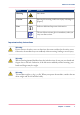
Notes for the reader Word Icon Indicates Warning Laser beam Caution Ignoring this warning could cause injury or damage to property. Note Indicates additional important information. The use of heat-resistant gloves is mandatory when you carry out these actions. Important safety instructions Warning: Do not remove the safety covers or deactivate the sensor switches for the safety covers. Otherwise, the machine may start suddenly without warning, leading to severe injury.
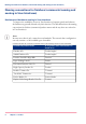
Naming conventions for finishers (commercial naming and naming in User Interfaces) Naming conventions for finishers (commercial naming and naming in User Interfaces) Hardware and hardware naming in User Interfaces To improve the readability of texts in User Interfaces of operator panels and software, the finishers are generally referred to by their function. The table below shows the naming conventions for finishers (commercial product names and the way these are referred to in User Interfaces).
Chapter 2 Parts and their functions
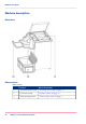
Machine description Machine description Illustration Main sections Main sections# 10 Section More information 1 Two-knife trim section ‘Two-knife trim section’ on page 11 2 Conveyor section ‘Conveyor section’ on page 13 3 Trim ejecting section ‘Trim ejecting section’ on page 15 Chapter 2 - Parts and their functions
Two-knife trim section Two-knife trim section Introduction Each booklet delivered from the upstream trimmer is trimmed along it's top and bottom. Then the booklet is delivered to the conveyor section. Illustration [11] Two-knife trim section Main parts Main parts# A Part Function Top cover The top cover gives access to the trimmer.
Two-knife trim section Part Function B Handle The handle lifts the booklet transport unit (TF2). C Booklet transport unit (TF2) If a booklet jam occurs in the two-knife trim section, you must press the handle and lift the booklet transport unit (TF2) to remove the jammed booklets. How to open the booklet transport unit (TF2): 1. Press the handle to the left. 2. Lift the booklet transport unit (TF2) up. D Trim knives The knives trim the top and bottom of each booklet.
Conveyor section Conveyor section Introduction The booklets delivered are laid out on the conveyor.
Conveyor section Main parts Main parts# Part Function A Handle (TE) Grip the handle and lift the roller unit when you remove the booklets from the conveyor. B Delivery transport rollers The delivery transport rollers hold the finished booklets. The position of the rollers is set automatically to match the booklet size. C Booklet detect sensor The sensor detects when the conveyor is full of stacked booklets.
Trim ejecting section Trim ejecting section Introduction The trim waste is ejected into the trimmer waste box through this section.
Trim ejecting section Main parts Main parts# Part Function A Trim Full sensor If trim waste is present between the sensor and the reflector, the operator panel displays the message 'Empty the two-knife trimmer waste box.'. B Delivery chute Trim waste is ejected into the trim box through this chute. C Trimmer waste box The trimmer waste box contains the trim waste.
Chapter 3 Operating procedures
Turn the trimmer on Turn the trimmer on How to turn on the trimmer 1. Put the On/Off button of Saddle Finisher-AF2 into the "I" position. 2. Press the On/Off button on top of the printer, next to the base of the operator panel. Result The trimmer will be turned on because the trimmer is connected to Saddle Finisher-AF2.
Operation while trimming Operation while trimming Introduction This section describes the main actions when using the trimmer.
Operation while trimming Empty the delivery tray When the machine stops because the delivery tray is full, you must remove the booklets from the delivery tray. The machine will restart automatically. Note: When you remove the booklets before the delivery tray is full, you can increase the productivity without interrupting the operation. Note: Be careful not to drop a booklet while removing it.
Operation while trimming [15] The covers of the trimmer # A Top cover B Transport section C Delivery section cover D Opening the transport unit Note: If a booklet jam occurs frequently, refer to ‘Clear a paper jam’ on page 27 for instructions on how to correct the problem.
Remove or install the delivery tray Remove or install the delivery tray Illustration [16] Remove the delivery tray A. Locking knobs B. Delivery tray How to remove the delivery tray 1. To remove the delivery tray, loosen the 2 locking knobs. 2. Lift the delivery tray up to remove. 3. Tighten the two locking knobs. How to install the delivery tray 1. To install the delivery tray, loosen the 2 locking knobs. 2. Lower the delivery tray to install. 3. Tighten the two locking knobs.
Chapter 4 Troubleshooting
Error messages Error messages Introduction When an error occurs and the machine does not work properly, the operator panel will display the message 'Call service.'. When this messages is displayed, keep in mind the following cautions. Warning: Do not plug in or pull out the power plug with wet hands. This may cause an electrical shock. Warning: When you pull the power plug out, be sure to hold the plug as you do so.
Overview of possible errors Overview of possible errors Introduction When an error occurs in the trimmer, the printer operator panel displays a corresponding message. The table below describes possible solutions for trimmer-related errors. Illustration [17] Error locations Possible errors Errors and solutions# Cause of error Solution The top cover is open. Close the top cover (1). The delivery tray is full.* Lift the E handle and remove the booklets from the conveyor section.
Overview of possible errors Cause of error Solution A booklet jam has occurred at the entrance of the two-knife trim section. • Open the delivery section cover (2) of the upstream trimmer. • Open the top cover (1). • Open the A and F2 transport unit, and remove the jammed booklet. • Reposition the A and F2 transport unit, and close the top cover (1) and the delivery section cover (2) to restart the printing. A booklet jam has occurred in the twoknife trim section. • Open the top cover (1).
Clear a paper jam Clear a paper jam Introduction Paper jams can occur at the following locations: # A Conveyor section B Trim section When a paper jam occurs, the jam is always caused by a paper chip jam or dirty transport belts. The table below describes these causes and the solutions.
Clear a paper jam How to clear a paper jam # Cause of jam Solution Paper chip jam • Open the transport unit. • Check if any paper chips are left on the booklet feed path. • Remove the paper chips. Transport belts are dirty 28 Chapter 4 - Troubleshooting Clean the transport belts. Contact your local authorized dealer.
Appendix A Specifications
Specifications Specifications Two-Knife Booklet Trimmer-A1 Note: Whenever a number of sheets is mentioned in the table below, the figure is based on media of 80 g/m² (20 lb Bond). Specifications of Two-Knife Booklet Trimmer-A1# Item Specifications Description Top-bottom trimmer Maximum number of sheets trimmable 50 sheets or 48 sheets + 2 sheets of 300 g/m² (110 lb Cover) Note: To prevent damage to cover sheets, it is recommended to use thicker sheets for covers than the other sheets in booklets.
Specifications Item Specifications Conveyor capacity 30 booklets containing 40 sheets of A4 / Letter when trimming 20 mm (0.79") of width in Booklet Trimmer-D1. Note: When the delivery tray is removed, the conveyor full condition is not detected. Continuous operation is possible. Machine dimensions (without conveyor section and delivery tray) WxDxH: 536 mm x 770 mm x 1,040 mm (21" x 30.
Index Index T Clear Paper chip jam ................................................27 Paper jam .......................................................27 Conversion table for commercial names and user interface names Conversion table for commercial names and user interface names .................................................8 Conveyor section Conveyor section ............................................13 D Delivery tray Install .............................................................22 Remove ...