Effective Date: June 1, 2018 GREASE MANAGEMENT Engineering grease ENDURA SECTION 22 13 23 GREASE INTERCEPTORS management solutions for plumbing and food service professionals tech-support@endurainterceptor.
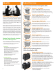
About Us Product Overview Hydromechanical Grease Interceptors (HGI) Endura® 7 - 10 Models 3907A02 - 7GPM (0.44 LPS) 2” (51 mm) connection 3910A02 - 10GPM (0.63 LPS) 2” (51 mm) connection Compact models use a development of the patented Endura baffle system to enhance separation performance at low flow rates. EZ-Clean tank design – Aids exterior cleaning.
Grease Interceptors – Generic Types The grease management industry has developed significantly in the past decade with not only more advanced and improved products but also development of performance standards and harmonization of common terms and references. Traditionally the term “Grease Trap” was commonly applied and is still used in the industry today.
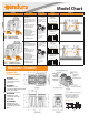
Model Chart Product Description - Compact tank / small footprint - Injection molded in proven engineered thermoplastics for strength and durability - EZ-Open cover latches 10,000 lb 4536 kg - Odor lock cover gasket 2000 lb 907 kg- Load rated cover supports up to 300 lb 300 lb (135kg) of pedestrian and 135 kg light duty traffic - EZ-Clean exterior tank profile with a Endura® Compact Grease Interceptor non-ribbed section at the lower two - 7 GPM 3907A02 - 10 GPM 3910A02 inches of the tank (Suffix “T” for th
In-Floor Extension Riser Flow Control Extension Standards Conformance Listings Thermal Capability 3-Part Master Format Specifications, CAD Drawings & BIM Drawings available at NYC Commonwealth of Massachusetts N/A Continuous discharge at 104˚C (220˚F) N/A * • Check local codes for acceptance of in-floor installation • Finish to floor level accommodating requisite materials, E.G. Tile, mortar, etc.
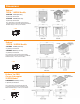
Dimensions Endura® 7GPM - 10GPM Models 3907A02 7GPM (0.44 LPS) 2” (51mm) connection 3910A02 10GPM (0.63 LPS) 2” (51mm) connection Notes: ACCESSIBLE FLOW CONTROL DEVICE (FCD) IS SUPPLIED FOR INSTALLATION UPSTREAM OF THE GREASE INTERCEPTOR (GI) -2” INLET/OUTLET MODELS 2” FCD Endura® 15GPM - 20GPM Models 3915A02 15GPM (0.94 LPS) 2” (51mm) connection 3920A02 20GPM (1.
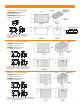
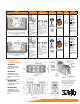
Endura® 25GPM Models 3925XTA02 25GPM (1.6 LPS) 2” (51mm) connection 3925XTA03 25GPM (1.6 LPS) 3” (76mm) connection 2” FCD 3” FCD A B A B 3925XTA02 (2”) 3925XTA03 (3”) 4” 12.5” 4.5” 12” Notes: ACCESSIBLE FLOW CONTROL DEVICE (FCD) IS SUPPLIED FOR INSTALLATION UPSTREAM OF THE GREASE INTERCEPTOR (GI) - 2” , 3” INLET/ OUTLET MODELS Endura® 35GPM Models 3935A03 35GPM (2.2 LPS) 3” (76mm) connection 3935A04 35GPM (2.
Model Chart Product 00 lb 35 kg 300 lb 135 kg 10,000 lb 4536 kg M 2000 lb 907 kg S 10,000 lb 4536 kg 00 lb Load Rating Load Rating 2000 lb 35 kgEndura® XL Grease Interceptor 907 kg - XL75 –300 75GPMlb 4075A04(T) - XL75 – 75GPM 4075A04M(T) 135 kg 00 lb 35 kg 300 lb 135 kg 10,000 lb 4536 kg 2000 lb 907 kg 10,000 lb 4536 kg S 00 lb M Load Rating Load Rating 2000 lb 35 kgEndura® XL Grease Interceptor 907 kg lb 40100A04(T) - XL100300 – 100GPM - XL100 – 100GPM 40100A04M(T) 135 kg Description Connectio
In-Floor Extension Riser Flow Control Extension Standards Conformance Listings Thermal Capability Remarks 3-Part Master Format Specifications, CAD Drawings & BIM Drawings available at Commonwealth of Massachusetts • Check local codes for acceptance of in-floor installation • Finish to floor level accommodating requisite materials, E.G. Tile, mortar, etc.
Key Design Considerations Sizing by Flow Rate It is recommended that HGI’s such as Endura® interceptors are initially sized by flow rate. The use of a flow control with a Hydromechanical Grease Interceptor is considered mandatory. Without a properly sized flow control, the discharge rate through into the interceptor may exceed the design rating of the unit, causing lower efficiencies and increase the risk of grease, passing into the downstream system. Be careful not to confuse liquid capacity and flow rate.
SizingforGreaseCapacity&Maintenance Sizing by DFU’s DFU’s: Based on the volume of wastewater discharge (gallons) into the interceptor Calculator expressed as discharge fixture units (DFU’s). DFU’s are identified in the currently published issue of Uniform Plumbing Code Ch.7 based on occupancy or use.
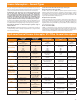
Technical Data CAPACITIES Endura 7 Endura 10 Endura 15 Endura 20 Endura 25LO Endura 25 • Part Number 3907A02 3910A02 3915A02 3920A02 3925A02LO 3925XTA02 (2”) 3925XTA03 (3”) US Gallons Per Minute - GPM (L/Sec) 7 (0.44) 10 (0.63) 15 (0.94) 20 (1.26) 25 LO (1.6) 25 (1.6) 35 (2.2) Min. Grease Capacity - lb (kg) 14 (6.35) 20 (9.07) 30 (13.6) 40 (18.1) 50 (22.68) 50 (22.68) 62.59 (28.39) Grease Capacity Actual (ASME A112.14.3) - lb (kg) † NSF ES 15741 31.95 (14.49) 38.07 (17.28) 35.
Flow Control Formats External (Supplied Standard with Endura 7 to Endura 50 Models) Hub x Hub format – Sch40 DWV. Nominal diameters 2”(Compact), 3” and 4”. For solvent weld within ABS or PVC DWV drainage systems, use appropriately approved solvent cement. NOTE: The Flow Control cannot be solvent welded directly to the interceptor.
Drain Cleanouts For installations below grade, most codes require the installation of a two way cleanout immediately before and after the respective inlet and outlet connections. These cleanouts will be extended to grade so as to remain accessible once the interceptor is operational.
Typical Installation • On Floor CAUTION: CLEARANCE REQUIRED 15” clearance (21” for 50GPM model) to remove the baffles for CAUTION cleaning and maintenance. • Flow Control Device • Semi Recessed Option • Grease Interceptor • Sink • Vented Waste • • Air Intake PDI recommends not to exceed 25ft (7.62m) horizontal run.
Low Profile The Endura® Lo-PRO is installed on floor. Ensure you design/locate the grease interceptor so as to allow for maintenance. Placement should allow the cover to be easily removed for cleaning. A minimum clearance of only 6 inches is required above the top of the Grease Interceptor to allow removal of the internal baffles for a complete cleanout. CAUTION: CLEARANCE REQUIRED 6” clearance above the grease interceptor required to CAUTION remove the baffles for cleaning and maintenance.
• In Floor Alternate • Fork Lift, Pump Truck Traffic Area Provision of a concrete pit with a load rated access cover will be required where pump CAUTION trucks of fork lifts travel. • Flow Control Device * Above grade installation preferred * • Sink • Grease Interceptor • Concrete pit • Vented Waste • Load Rated Access Cover (supplied by others) • Air Intake • Cleanout required in most jurisdictions • Hanger (Supplier by installer) PDI recommends not to exceed 25ft (7.62m) horizontal run.
• Interior or Exterior Below Grade Installations - High Capacity • Concrete Slab Detail For Traffic Loading Concrete to be 28 day compressive strength to 4000 PSI. Reinforcement with No.4 rebar (1/2”) grade 60 steel per ASTM A615: connected with tie wire. Rebar to be 2½” from edge of concrete. Rebar spacing 12” grid. 4” spacing around access openings. • Concrete Pad must extend min. 18” outside the unit footprint • No.
Outlet Inlet Cleanout G • Sampling Well - High Capacity RE A SE IN TE RC EP TO Min. 6" G RE A SE IN TE RC EP TO R Outlet Min. Inlet LOCATION: Sampling Well Min. 12" G Outlet RE A SE IN TE 6" Min. 12" RC EP TO G RE A SE IN TE RC EP TO R R RE A SE IN TE RC EP TO TO SE IN TE RC EP G TO RE R A R TO EP EP RC RC TE TE IN IN SE SE A R R RE should be located as close as possible to the outlet connection of the grease interceptor.
Specifications Endura® brand products are manufactured by Canplas Industries Ltd SECTION 22 13 23 GREASE INTERCEPTORS Copyright 2014 - 2016 ARCAT, Inc. - All rights reserved PART 1 GENERAL 1.1 SECTION INCLUDES A. Grease interceptors (Hydromechanical). B. C. Email: tech-support@endurainterceptor.com; Substitutions: Not permitted. Requests for substitutions will be considered in accordance with provisions of Section 01 60 00 - Product Requirements. 2.2 GREASE MANAGEMENT A.
removable for the purposes of maintenance, providing 2. Model 3915A02 - Endura® 15GPM/30LB unrestricted upstream and downstream drain access. The (No-Hub connection – Mechanical Joint coupling) grease interceptor shall be certified to the current version of the Model 3915A02T - Endura® 15GPM/30LB (Threaded connection). PDI-G101, ASME A112.14.3 or CSA B481.1 and where locally Model 3915A02S - Endura® 15GPM/30LB (Spigot connection). a. Flow Rate: 15 US Gallons per Minute (0.
and retain the covers to the tank, but allow consistent i. Modular Riser Extensions: For use with in-floor installations; sized removal and replacement of the cover without operational during installation to project requirements. Use up to three (3) full risers per installation (18” maximum height adjustment) Provide compromise. Functional elements such as baffles will be with 1 inch markers/ribs on riser to aid height adjustment.
G. Product: Endura®XL Grease Interceptor 100 GPM Grease Interceptor as manufactured by Canplas Industries Ltd. 1. The unit shall be comprised of engineered thermoplastics to withstand prolonged intermittent influent discharge temperatures up to 160 degree F (71 degree C) comprising of two load rated covers capable of exceeding loads of 20,000 lb (9072 kg) and incorporating an operationally air tight seal.
Endura® Grease Interceptors are manufactured in a ISO 9001 and 14001 registered facility. Our quality management system has been registered for the design, manufacture and distribution of high quality injection molded products used in plumbing, industrial, ventilation and central vacuum applications. www.EnduraInterceptor.com ® www.arcat.com See our course online at: www.csc-dcc.ca www.csinet.org Canplas Industries Ltd.