
Use and Care Manual

- 2 -
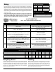
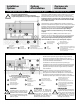
Sizing
Mop Sink Sizing Guide
Size LPS US/GPM
2” 84 22
3” 142 37.5
4” 170 45
Floor Drains & Floor Sinks
Take the volume of water produced by the
number of hose bibs (ie 1.5-2.0 gpm per 3/4”
faucet)
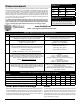
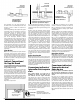
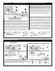
Table A - Procedure for Sizing Grease Interceptors
STEP FORMULA EXAMPLE
1 Determine cubic content of xture by multiplying length x
width x depth
A sink 24” long by 20” wide by 12” deep.
Cubic content: 24 x 20 x 12 = 5,760 cubic inches
(61.0 x 50.8 x 30.48 cm
3
)
2 Determine capacity in gallons.
1 gallon = 231 cubic inches
Contents in gallons:
5,760 / 231 = 24.9 gallons
(94,451.42 / 1,000 = 94.45 litres)
3 Determine actual drainage load.
The xture is normally lled to approximately 75% of capacity
with water as the items being washed displace about 25% of
the total xture content.
Actual drainage load = 75% of xture capacity
Actual drainage load:
.75 x 24.9 = 18.7 gallons
(0.75 x 94.45 = 70.84 litres)
4
Determine ow rate and drainage period.
In general, good practice dictates a one minute drainage pe
-
riod; however, where conditions permit, a two minute drainage
period is acceptable. Drainage period is dened as the actual
time required to completely drain the xture.
Flow rate = Actual Drainage Load
Drainage Period
Calculate ow rate for one minute drainage period:
18.7 / 1 = 18.7 g.p.m. ow rate
(70.84 / 1 min. = 70.84 l.p.m.)
Calculate ow rate for two minute drainage period:
18.7 / 2 = 9.4 g.p.m. ow rate
(70.84 / 2 min. = 35.42 l.p.m.)
5 Select Interceptor.
From Table B select the interceptor with a ow rating at least
equal to the calculated ow rate. When the calculated ow rate
falls between two sizes, select the larger of the two
interceptors.
For a one minute drainage period:
18.7 g.p.m. (70.84 l.p.m.) ow rate = 20 g.p.m. G.I.
For a two minute drainage period:
9.4 g.p.m. (35.42 l.p.m.) ow rate = 10 g.p.m. G.I.
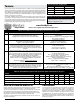
Table B - Procedure for Sizing Grease Interceptors
PDI Size Symbol 4 7 10 15 20 25 35 50
Flow Rate US Gallons per Minute (GPM) 4 7 10 15 20 25 35 50
Flow Rate Liters per Second (LPS) .25 .44 .63 .95 1.26 1.58 2.20 3.16
Grease Capacity Pounds (Lbs) 8 14 20 30 40 50 70 100
Grease Capacity Kilograms (Kgs) 3.63 6.35 9.07 13.61 18.14 22.68 31.75 45.36
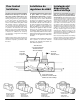
Sampling Access
Some municipalities require a sampling port to monitor euent quality. If
the unit is on the oor, or semi-recessed into the oor, a cleanout tee can
be installed downstream of the Grease Interceptor. If the unit is installed
in the oor, a backwater with its apper removed, makes an eective
collection port. Like the FCD the backwater valve can be extended to
nish oor level using a sleeve kit.
Venting
Grease Interceptors must have a vented waste, sized in accordance
with local code requirements for venting interceptors to retain a
water seal and prevent siphoning. Most codes dictate that two
vents be installed, one upstream and one downstream of the
grease interceptor. The upstream vent must not be placed between
the air intake and the grease interceptor.
For Grease Interceptor sizing, please reference the Sizing Guide or the Plumbing &
Drainage Institute Standard PDI-G 101. Without a properly sized ow control, the ow
through the interceptor may exceed the rating of the unit, causing lower eciencies
and allowing grease to pass through the interceptor into the downstream piping. Be
careful that you do not confuse liquid capacity and ow capacity. Liquid capacity is
rated in litres or gallons while ow capacity is rated in gpm (gallons per minute) or L/
sec (litres per second).
If sizing indicates that a larger Grease Interceptor is required, you maybe able to
compromise to a smaller unit by adopting to a 2 minute drain down time in your
sizing calculation. Although the smaller unit will be less expensive, the grease
capacity of a smaller unit will dictate the cleaning frequency required.
Email: tech-support@endurainterceptor.com
www.SizeMyGI.net