Baseline Switch 2250 Plus User Guide Installationsanleitung 3C16476CS http://www.3com.com/ Part No. 10015237 Rev.
3Com Corporation • 350 Campus Drive • Marlborough • MA USA 01752-3064 Copyright © 2006, 3Com Corporation. All rights reserved. No part of this documentation may be reproduced in any form or by any means or used to make any derivative work (such as translation, transformation, or adaptation) without written permission from 3Com Corporation.
CONTENTS Supplying Power to the Switch 16 Checking for Correct Operation 16 Connecting a Network Device 17 Using SFP Transceivers 18 Approved SFP Transceivers 18 Inserting an SFP Transceiver 18 Removing an SFP Transceiver 19 Performing Spot Checks 19 ABOUT THIS GUIDE Conventions 5 Related Documentation 6 Documentation Comments 6 1 INTRODUCING THE BASELINE SWITCH Overview of the Baseline Switch 2250 Plus 7 Features and Capabilities 7 Autosensing of MDI/MDIX Connections 7 Autonegotiating 10/100 Mbps Ports
Backup Configuration 30 Restore Configuration 30 Firmware Upgrade 31 Initialize 31 Reboot 32 System Access 32 System Time 34 SNMP 34 Configuring VLANs 35 VLAN 36 Forwarding Tagged/Untagged Frames 39 Sample VLAN Configurations 40 Spanning Tree 41 IGMP Snooping 42 IGMP Query 42 Broadcast Storm 43 Configuring Port Settings 43 Administration 43 Speed/Duplex for 1000 Mbps Connections Link Aggregation 45 Spanning Tree per Port 47 Port Mirroring 49 QoS VoIP Traffic Settings 50 Security 53 RADIUS Client 53 802.
ABOUT THIS GUIDE This guide describes how to install your Switch and perform initial management configurations. This guide is intended for use by network administators who are responsible for installing and setting up network equipment. Consequently, it assumes a basic working knowledge of LANs (local area networks).
ABOUT THIS GUIDE Related Documentation In addition to this guide, each 3Com Baseline Switch 2250 Plus documentation set includes the following: ■ Online Help – Accessible from the Web interface, provides information that helps you perform tasks using the Web interface. ■ Release Notes – Provide information about the current software release, including new features, modifications, and known problems. Documentation Comments Your suggestions are very important to us.
1 INTRODUCING THE BASELINE SWITCH This chapter provides an overview of the features and capabilities of the 3Com® Baseline Switch 2250 Plus. It also identifies the contents of the Switch package and helps you get to know the physical features of the device. Overview of the Baseline Switch 2250 Plus The 3Com® Baseline Switch 2250 Plus is a versatile, easy-to-use unmanaged switch.
CHAPTER 1: INTRODUCING THE BASELINE SWITCH SFP Ports The two SFP ports support fiber Gigabit Ethernet short-wave (SX) and long-wave (LX) SFP transceivers in any combination. This offers you the flexibility of using SFP transceivers to provide connectivity between the Switch and a 1000 Mbps core network. When an SFP port is in operation, the corresponding 10/100/1000BASE-T port is disabled.
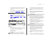
Physical Features available communication paths between switches and to determine the best available path and block less optimal paths. For information on configuring BPDU forwarding and blocking, refer to “Spanning Tree” on page 41. Physical Features Figure 1 shows the front and rear panels of the Switch. The numbers in this diagram refer to numbered sections in “Front Panel” on page 9 and “Rear Panel” on page 12. Figure 1 Front and Rear Panels 9 to a traditional PBX or public telephone network.
CHAPTER 1: INTRODUCING THE BASELINE SWITCH Each port also supports automatic MDI/MDI-X detection and can be connected to either a 10BASE-T, or a 100BASE-TX device. The two SFP ports support fiber Gigabit Ethernet short-wave (SX) and long-wave (LX) SFP transceivers in any combination. This offers you the flexibility of using SFP transceivers to provide connectivity between the Switch and remote 1000 Mbps workgroups or to create a high-capacity aggregated link backbone connection.
Physical Features 11 Status Meaning Status Meaning Flashing Yellow Packets are being received or transmitted on the port at 10 Mbps Flashing Yellow to Green Port disabled or link loopback error Off Link not established, either nothing is connected to the port, or there is a problem. Off Link not established, either nothing is connected to the port, or there is a problem.
CHAPTER 1: INTRODUCING THE BASELINE SWITCH (5) Power LED The Power LED shows the power status of the Switch. Table 7 Power LED Status Meaning Green The unit is powered on and ready for use Flashing Green Power-on self-test is in progress Yellow Power-on self-test or loopback test failed. If this occurs, reset the Switch to factory defaults.
2 INSTALLING THE SWITCH This chapter contains information that you need to install and set up the Switch. It covers the following topics: ■ Positioning the Switch ■ Rack-Mounting or Free-Standing ■ Supplying Power to the Switch ■ Connecting a Network Device ■ Connecting a Network Device ■ Performing Spot Checks Before You Begin WARNING: Safety Information.
CHAPTER 2: INSTALLING THE SWITCH 3Com empfiehlt das Sie 25mm (1 Inch) Zwischenraum sicherstellen. recommends that you provide a minimum of 25 mm or 1 in. clearance). ■ The air is as free of dust as possible. ■ Die Luft so frei wie möglich von Staub ist. ■ Temperature operating limits are not likely to be exceeded. It is recommended that the unit is installed in a clean, air conditioned environment. ■ Es unwahrscheinlich ist das die Betriebstemperatur überschritten wird.
Rack-Mounting or Free-Standing To rack-mount the Switch: 1 Place the unit the right way up on a hard, flat surface with the front facing towards you. 2 Locate a mounting bracket over the mounting holes on one side of the unit. 3 Insert the two screws supplied in the mounting kit and fully tighten with a suitable screwdriver. Figure 2 Inserting the Screws Baseline Switch 2816-SFP Plus 15 Montagesatz Anweisungen Der Switch wird mit zwei Halterungen und vier Schrauben geliefert.
CHAPTER 2: INSTALLING THE SWITCH Placing Units On Top of Each Other If the Switch units are free-standing, up to four units can be placed one on top of the other. If you are mixing a variety of Baseline and SuperStack units, the smaller units must be positioned at the top. If you are placing Switch units one on top of the other, you must use the self-adhesive rubber pads supplied. Apply the pads to the underside of each Switch, sticking one in the marked area at each corner.
Connecting a Network Device Color State Yellow Power-on self-test or loopback test failed. This can happen if a ports or ports fail when the Switch was powered on. Off The unit is not receiving power: ■ ■ Verify that the power cord is connected correctly, and then try powering on the Switch again If the Switch still does not operate, contact your 3Com network supplier If POST fails, try the following: ■ ■ Power off the Switch, and then power it on again.
CHAPTER 2: INSTALLING THE SWITCH Using SFP Transceivers The following sections describe how to insert and remove an SFP transceiver from an SFP slot. SFP transceivers are hot-insertable and hot-swappable. You can remove them from and insert them into any SFP port without having to power off the Switch. fiber-optic cable or to multimode fiber using a conditioned launch cable. If the SFP transceiver is faulty, it will not operate within the Switch. See “Troubleshooting” on page 59.
Performing Spot Checks CAUTION: SFP transceivers are keyed and can be properly inserted only one way. If the transceiver does not click when you insert it, remove it, turn it over, and then re-insert it. 3 Remove the plastic protective cover, if fitted. 4 Connect the fiber cable. 5 The transceiver connects to the network using a duplex LC connector. Attach a male duplex LC connector on the network cable into the duplex LC connector on the transceiver.
CHAPTER 2: INSTALLING THE SWITCH
3 CONNECTING TO THE WEB INTERFACE The Switch has a built-in Web interface that you can use to set the admin password, change the IP address that is assigned to the Switch, and configure its advanced settings. If you only want the Switch to function as a basic layer 2 switch, you do not need to access the Web interface and configure the Switch. This chapter provides information on how the gain access to the Web interface using the Discovery application.
CHAPTER 3: CONNECTING TO THE WEB INTERFACE The Welcome screen of Discovery appears. Figure 6 Discovered Devices Screen Figure 5 Welcome Screen of Discovery 3 On the Discovered Devices screen, click Baseline 2 If the computer has multiple network adapters, select the adapter that connects the computer to the Switch, and then click Next. If the computer has only one adapter, click Next. Discovery searches the network for 3Com devices.
Logging On to the Web Interface Logging On to the Web Interface After the Web interface loads in your Web browser, the first page that appears is the logon screen. On this screen, you need to enter the administration user name and password to gain access to the Web interface. The logon screen also displays the IP address that the Switch is currently using.
CHAPTER 3: CONNECTING TO THE WEB INTERFACE Table 10 lists the available items on the menu. Table 10 Available Menu Items Menu Item Description Device Summary Administration IP Setup SNMP Contains tabs that allow you to: ■ Save Configuration Menu Item Provide a summary of the Switch’s basic settings and versions of current components. ■ Set the polling interval in seconds. ■ Display the description for each color coded port. Device VLAN Saves the Switch’s configuration. Manages the device.
Navigating the Web Interface Menu Item Link Aggregation Spanning Tree per Port Description Contains tabs that allow you to: ■ Display 802.1X information. ■ Create an aggregation group. ■ ■ Modify the port memberships. Display 802.1X detailed information per port. ■ Remove an aggregation group. ■ Configure 802.1X settings. Contains tabs that allow you to: Display Switch monitoring information. Display selected spanning tree information for every port.
CHAPTER 3: CONNECTING TO THE WEB INTERFACE Accessing the Interface Without Using Discovery The Discovery application works by automatically detecting the IP address that is assigned to the Switch, and then using that address to connect to the Web interface. If you know the Switch’s IP address, you can access the Web interface without using Discovery. This section describes how to access the interface directly, without using Discovery.
CONFIGURING THE SWITCH 4 This chapter provides information on how to configure the Switch’s advanced features. Topics include: Device Summary Information The Device Summary screen, which automatically loads after you log on to the Web interface, provides a snapshot of the Switch’s basic settings and versions of current components. ■ Device Summary Information ■ Administration Settings ■ Configuring VLANs ■ Configuring Port Settings Click Device Summary on the menu.
CHAPTER 4: CONFIGURING THE SWITCH Figure 9 Device View To set the polling interval: 1 Click the Device Summary menu, click Polling Interval tab. 2 Enter a number between 10 to 180 seconds for the polling interval. Enter a 0 to disable polling. Color Key Description of the color coding. Figure 11 Color Key If you request for technical assistance from 3Com Support, you may be asked to print out the information on this screen.
Administration Settings Administration Settings The Administration menu includes eight administration items: ■ IP Setup ■ Backup Configuration ■ Restore Configuration ■ Firmware Upgrade ■ Initialize ■ Reboot ■ System Access ■ System Time ■ SNMP Modifying the IP Address Settings To enable devices on the network to communicate with the Switch, you need to assign an IP address to it — either by DHCP or by assigning a static IP address.
CHAPTER 4: CONFIGURING THE SWITCH IP Setup To set the IP address for the Switch: 1 Click Administration, then IP Setting on the menu. The IP Settings screen appears. Follow the IP Setup Wizard to complete the setup. Backup Configuration To save the Switch configuration settings: 1 Click Administration, then Backup Configuration on the menu. The Backup Configuration screen appears. Figure 13 Backup Configuration This wizard can also be used to set system name, location and contact information.
Administration Settings 3 Click Restore to copy the configuration back to the Switch. For security purposes, restoring the configuration does not change the password. Firmware Upgrade The Upgrade facility allows you to install on the Switch any new releases of system firmware that 3Com may make available. Newer versions of firmware can be downloaded via HTTP and copied to the Switch; the Switch will restart and apply the newer system firmware version.
CHAPTER 4: CONFIGURING THE SWITCH your computer to re-establish communication with the Switch. Reboot Clicking on Administration, then Reboot on the menu has the same effect as power cycling the unit. No configuration information will be lost. Reboot the Switch if you are experiencing problems and you want to re-establish your Internet connection.
Administration Settings Create User 33 Figure 18 Modify User Screen This page allows you to create a user and define the access level and password for that user. Figure 17 CreateUser Screen Remove User To remove a user from the Switch, click on the user name, then click Remove. Modify User This page allows you to modify a user’s access level and password.
CHAPTER 4: CONFIGURING THE SWITCH System Time Click Administration, then System Time on the menu. This screen allows you to set the system time. You can set the Year, Month, Day, Hours, Minutes, and Seconds. Summary Displays the list community access strings. Figure 21 SNMP Summary Screen Figure 20 System Time Screen Setup SNMP Enable or disable the SNMP Agent Status. Simple Network Management Protocol (SNMP) is a communication protocol designed specifically for managing devices on a network.
Configuring VLANs Figure 23 SNMP Add Screen 35 Configuring VLANs A virtual LAN (VLAN) is a collection of network nodes that share the same collision domain, regardless of their physical location or connection point in the network. A VLAN serves as a logical workgroup with no physical barriers, and allows users to share information and resources as though located on the same LAN. SNMP Remove This page allows you to remove community strings.
CHAPTER 4: CONFIGURING THE SWITCH VLAN Available option on the Setup screen include: Click Device, then VLAN on the menu. A screen appears with seven tabs that include: ■ Setup ■ Modify VLAN ■ Modify Port ■ Rename ■ Remove ■ Port Detail ■ VLAN Detail Setup Use the Setup screen to create VLANs on the Switch. To propagate information about VLAN groups used on this Switch to external devices, you must specify a VLAN ID for each VLAN.
Configuring VLANs Figure 26 Modify VLAN Screen 37 Modify Port Use the Modify Port screen to modify the VLAN membership of a port. Figure 27 Modify Port Screen 1 Select a membership use. Available options for each 1 Enter a set of VLANs or select all VLANs to configure, then click Select. port include (only one option can be associated with a single port): 2 From the drop down menu, select a VLAN to modify. ■ Not a member 3 Select a membership use.
CHAPTER 4: CONFIGURING THE SWITCH Rename Remove Use the Rename screen to change the name of a VLAN. Use the Remove screen to remove a VLAN. Figure 29 Remove Screen Figure 28 Rename Screen 1 Enter a set of VLANs or select all VLANs to add to the remove list, then click Select. 1 Enter a set of VLANs or select all VLANs to add to the rename list, then click Select. 2 From the list of selected VLANs, choose a VLAN to rename. Enter a new VLAN name and click Apply.
Configuring VLANs Port Detail 39 Figure 31 VLAN Detail Screen Choose a port to display the tagged and untagged VLAN memberships it is associated with. Figure 30 Port Detail Screen VLAN Detail Use this screen to display detailed VLAN information. 1 Enter a set of VLANs or select all VLANs to add to the details list, then click Select. 2 From drop down menu, choose a VLAN to display the tagged and untagged VLAN memberships it is associated with the ports on the switch.
CHAPTER 4: CONFIGURING THE SWITCH The Switch will only forward a frame to ports that are members (tagged or untagged) of the VLAN to which the frame is assigned. If the port is an untagged member, the egress frame will be stripped of the VLAN tag and forwarded as untagged. However, if the port is a tagged member, the egress frame is forwarded as tagged. VLAN1 and the ports on VLAN2 cannot communicate with each other, do the following: 1 Create a new VLAN and set the VLAN ID to 2.
Configuring VLANs Figure 33 Tagged VLAN Configuration 41 4 Connect the Tagged port on Switch 1 (in this example, port 16) to the Tagged port on Switch 2 (in this example, port 8). Those ports on Switch 1 that are members of VLAN2 can now communicate with those ports on Switch 2 that are members of VLAN2. Spanning Tree Spanning tree is a bridge-based system for providing fault tolerance on networks and can be used to detect and disable network loops.
CHAPTER 4: CONFIGURING THE SWITCH After all the bridges on the network have determined the configuration of their ports, each bridge only forwards traffic between the Root Port and the ports that are the Designated Bridge Ports for each network segment. All other ports are blocked, which means that they are prevented from forwarding traffic. To use spanning tree, choose enabled from the drop State down menu, fill in the setup parameters, and click Apply. to receive the multicast service.
Configuring Port Settings Broadcast Storm Use the Broadcast Storm page to set the Switch’s broadcast storm control and threshold limits. A broadcast storm is an incorrect packet sent out on a network that causes most hosts to respond all at once, typically with wrong answers that start the process over again. Broadcast storms use substantial network bandwidth and may cause network time-outs. 43 current connection status of each port or shut down or disable ports.
CHAPTER 4: CONFIGURING THE SWITCH Figure 38 Port Administration Summary Screen Figure 39 Port Administration Detail Screen Setup Use the Setup tab to configure the port settings. The following options are available: ■ Port State – Enables and disables the port. ■ Flow Control – Enables and disables flow control for the entire Switch. When flow control is enabled, the Switch regulates the packet flow so that a sending device does not transmit more packets than a receiving device can process.
Configuring Port Settings ■ Duplex – Sets the duplex mode of the port. Available options include auto, half, and full. If you modify any of these settings, click Apply to save your changes. Figure 40 Port Administration Setup Screen 45 CAUTION: Before manually setting a port to full-duplex, verify that the device connected to the port is also manually set to the same speed and duplex setting.
CHAPTER 4: CONFIGURING THE SWITCH Guidelines for Creating Trunks ■ Any port on the Switch can be used for creating a trunk. ■ This switch supports a maximum of four trunks. ■ Each trunk may contain up to four members. ■ A port may only be a member of one trunk at any one time. ■ All ports in a trunk must be configured in an identical manner, including communication mode (that is, speed, duplex mode and flow control).
Configuring Port Settings Modify 47 Figure 44 Link Aggregation Remove Screen Use the Modify tab reassign port members to a link aggregation group. Figure 43 Link Aggregation Modify Screen To remove a link aggregation group: 1 From the link aggregation group list, select the aggregated group to remove. 2 Click Remove. Spanning Tree per Port To modify a link aggregation group: 1 Select the aggregation group to modify, then click Select. 2 Select the ports to add to the goup. 3 Click Apply.
CHAPTER 4: CONFIGURING THE SWITCH the Root Bridge generates BPDUs (Bridge Protocol Data Units) on all ports at a regular interval known as the Hello Time. All other spanning tree-compliant devices on the network have a designated Root Port. This is the Port nearest the Root Bridge and it is used for receiving the BPDUs initiated by the Root Bridge. If a bridge does not get a Hello BPDU after a predetermined interval, the bridge assumes that the link to the Root Bridge is down.
Configuring Port Settings Figure 46 Spanning Tree Detail Screen 49 device with the lowest MAC address will then become the root device. If you modify any of these settings, click Apply to save your changes. Figure 47 Spanning Tree Setup Screen Setup Use the Setup tab to configure the spanning tree settings for each port. The following options are available: ■ Status – Enables and disables spanning tree for the port. ■ Edged Port – Enables and disables edged port for the port.
CHAPTER 4: CONFIGURING THE SWITCH Figure 48 Port Mirroring Screen QoS VoIP Traffic Settings Using the Web interface, you can configure the Voice over Internet Protocol (VoIP) settings. The QoS VoIP Traffic Setting menu includes six tabs: To set up port mirroring: 1 Connect a network analyzer to a port. 2 Access the Web interface. Click Port, then Port Mirroring on the menu. The Port Monitoring Setup Screen appears. 3 Select the port number under Monitor Port to which you want to monitor.
QoS VoIP Traffic Settings Setup Use the Setup tab to configure the global settings for Voice VLAN. The following options are available: ■ Voice VLAN Status – Enable or disable Voice VLAN for the switch. ■ Voice VLAN ID – Input the Voice VLAN ID for the switch. ■ Voice VLAN Aging Time – Input the aging time. To configure the Voice VLAN settings for the ports: 1 Select Voice VLAN Mode and Security settings. 2 Select the ports you would like to apply these settings to. 3 Click Apply.
CHAPTER 4: CONFIGURING THE SWITCH Figure 52 QoS Port Detail Screen OUI Modify Use the OUI Modify tab to add to the list of Organizational Unique Identifier. The following options are available: ■ Telephony OUI – Input a new company identifier to add to the list. ■ Description – Input a description for the new company identifier. To add to the OUI list: 1 Enter a Telephony OUI and description.
Security Security 53 Figure 55 RADIUS Client Detail Screen Using the Web interface, you can configure the RADIUS Client and 802.1X settings. The Security menu includes two items: ■ RADIUS Client ■ 802.1X Settings RADIUS Client Remote Authentication Dial-in User Service (RADIUS) is a logon authentication protocol that uses software running on a central server to control access to RADIUS-aware devices on the network.
CHAPTER 4: CONFIGURING THE SWITCH Figure 56 RADIUS Client Configure Screen Figure 57 802.1X Summary Screen 802.1X Settings Detail The IEEE 802.1X (dot1x) standard defines a port-based access control procedure that prevents unauthorized access to a network by requiring users to first submit credentials for authentication. The 802.1X settings menu includes three tabs: ■ Summary ■ Detail ■ Setup Summary Use the Summary tab to display the 802.1X authentication settings.
Security Setup ■ Max Count – The maximum number of hosts that can connect to a port when the Multi-Host operation mode is selected. (Range: 1-1024; Default: 5) ■ Reauthentication Period – Sets the time period after which a connected client must be re-authenticated. (Range: 1-65535 seconds; Default: 3600 seconds) ■ Quiet Period – Sets the time that a switch port waits after the Max Request Count has been exceeded before attempting to acquire a new client.
CHAPTER 4: CONFIGURING THE SWITCH Monitoring Using the Web interface, you can display address table information and cable diagnostics. The Monitoring menu includes two items: ■ Address Table ■ Cable Diagnostics Cable Diagnostics The Switch provides cable diagnostic, which helps you detect and resolve issues with the attached cables.
Monitoring Diagnostics Use the Diagnostics tab to display individual port information on Test Result, Cable Fault Distance, and Last Update.
CHAPTER 4: CONFIGURING THE SWITCH
5 TROUBLESHOOTING This chapter lists some issues that you may encounter while installing, using, and managing the Switch, with suggested courses of corrective action to take. If you encounter an issue that is not listed here and you cannot solve it, check the 3Com Knowledgebase at http://knowledgebase.3com.com before contacting your local technical support representative. For more information on how to obtain support for your Switch, refer to Appendix A.
CHAPTER 5: TROUBLESHOOTING Forgotten Static IP Address ■ If you forget the static IP address that you assigned to the Switch and you need to access the Web interface, use the Discovery application to automatically detect the IP address and connect to the interface. For information on using the Discovery application, refer to “Running the Discovery Application” on page 21. Solving LED Issues This section lists some issues that are related to the LEDs on the front panel of the Switch.
If the Problem Persists Ensure that the connected device has either: ■ Autonegotiation enabled, or ■ The ports are configured for half-duplex operation All ports appear to show continual activity. There may be broadcast storms on the network. Remove port connections one at a time, waiting a few seconds between each port. If the LEDs go off after removing a port connection, the device that was connected to that port is introducing an excessive amount of broadcast frames to the network.
CHAPTER 5: TROUBLESHOOTING
A OBTAINING SUPPORT FOR YOUR PRODUCT Register Your Product Warranty and other service benefits start from the date of purchase, so it is important to register your product quickly to ensure you get full use of the warranty and other service benefits available to you. Warranty and other service benefits are enabled through product registration. Register your product at http://eSupport.3com.com/. 3Com eSupport services are based on accounts that you create or have authorization to access.
APPENDIX A: OBTAINING SUPPORT FOR YOUR PRODUCT at http://eSupport.3com.com/, or under the Product Support heading at http://www.3com.com/ Software Upgrades are the software releases that follow the software version included with your original product. In order to access upgrades and related documentation you must first purchase a service contract from 3Com or your reseller.
Contact Us . Country Telephone Number Asia, Pacific Rim Telephone Technical Support and Repair Australia Hong Kong India Indonesia Japan Malaysia New Zealand Pakistan Philippines P.R. of China Singapore S.
APPENDIX A: OBTAINING SUPPORT FOR YOUR PRODUCT Country Telephone Number Country Telephone Number Antigua Argentina Aruba Bahamas Barbados Belize Bermuda Bonaire Brazil Cayman Chile Colombia Costa Rica Curacao Ecuador Dominican Republic Guatemala Haiti Honduras Jamaica Martinique Mexico Nicaragua Panama Paraguay Peru Puerto Rico Salvador Trinidad and Tobago Uruguay Venezuela Virgin Islands 1 800 988 2112 0 810 444 3COM 1 800 998 2112 1 800 998 2112 1 800 998 2112 52 5 201 0010 1 800 998 2112 1 800
B SAFETY INFORMATION Important Safety Information Please refer to the safety information found in the 3Com Switch Family Safety and Regulatory Information manual included with this product. You can find the 3Com Switch Family Safety and Regulatory Information manual on the product CD-ROM that was included with your switch. You can also download the safety manual from the 3Com Web site: www.3Com.
APPENDIX B: SAFETY INFORMATION
C TECHNICAL INFORMATION Physical Related Standards The 3Com Baseline Switch 2250 Plus has been designed to the following standards: Functional ISO 8802-3, IEEE 802.3 (Ethernet), IEEE 802.3u (Fast Ethernet), IEEE 802.3ab (Gigabit Ethernet), IEEE 802.3x (Flow Control), IEEE 802.1D (Bridging) MAC Address 4096 Safety UL/CUL (UL60950-1, CSA22.
APPENDIX C: TECHNICAL INFORMATION
GLOSSARY 10BASE-T The IEEE specification for 10 Mbps Ethernet over Category 3, 4 or 5 twisted pair cable. 100BASE-TX The IEEE specification for 100 Mbps Fast Ethernet over Category 5 twisted-pair cable. 1000BASE-LX IEEE 802.3z specification for Gigabit Ethernet over 9/125 micron core single-mode fiber cable. 1000BASE-SX IEEE 802.3z specification for Gigabit Ethernet over two strands of 50/125 or 62.5/125 micron core multimode fiber cable. 1000BASE-T IEEE 802.
GLOSSARY category 5e cables One of five grades of Twisted Pair (TP) cabling defined by the EIA/TIA-568 standard. Category 5e can be used in Ethernet (10BASE-T), Fast Ethernet (100BASE-TX) and Gigabit Ethernet (1000BASE-T) networks, and can transmit data at speeds of up to 1000 Mbps. Ethernet address See MAC address. Fast Ethernet An Ethernet system that is designed to operate at 100 Mbps.
GLOSSARY standard way for VLANs to communicate across switched networks. IP Address Internet Protocol Address. A unique identifier for a device attached to a network using TCP/IP. The address is written as four octets separated with periods (full-stops), and is made up of a network section, an optional subnet section and a host section. IEEE 802.1p An IEEE standard for providing quality of service (QoS) in Ethernet networks.
GLOSSARY Most devices that connect to a LAN have a MAC address assigned to them as they are used to identify other devices on a network. MAC addresses are 6 bytes long. SFP Small Form Factor Pluggable (SFP) Connectors are based on an open standard that enables hot swapping of various types of fiber optic and copper-based transceivers into the host equipment.
GLOSSARY developed for the interconnection of networks. Originally a UNIX standard, TCP/IP is now supported on almost all platforms, and is the protocol of the Internet. TCP relates to the content of the data travelling through a network — ensuring that the information sent arrives in one piece when it reaches its destination. IP relates to the address of the end station to which data is being sent, as well as the address of the destination network.
GLOSSARY
INDEX Numbers E L 1000BASE-LX 71 1000BASE-SX 71 1000BASE-T 71 100BASE-TX 71 10BASE-T 71 Ethernet 72 LAN defined 73 LED issues 60 LEDs Link/Activity 10 Module Active 11 Power 12 link aggregation 45 local area network 73 A auto IP configuration 29 default IP address 29 default mask 29 autonegotiation 7 autosensing 7 B F Fast Ethernet 72 forgotten IP address 59 forgotten password 59 free-standing 14 front panel Link/Activity LEDs 10 Module Active LEDs 11 Power LED 12 RJ-45 ports 11 self-adhesive pads
INDEX changing 32, 34 default (blank) 32 setting 28 physical features 9 port settings configuring 43, 50, 53 ports RJ-45 11 SFP 8, 10 positioning 13 POST 16 powering on 16 power-on self-test See POST protocol defined 74 R rack-mounting 14 rear panel power supply 12 Recovery button 12 resetting to factory defaults 59 RJ-45 defined 74 ports 11 S server defined 74 SFP ports 8, 10 SFP transceivers 18 approved (supported) 18 inserting 18 removing 19 spot checks 19 subnet mask 74 switch defined 74 T TCP/I
REGULATORY NOTICES FCC STATEMENT This equipment has been tested and found to comply with the limits for a Class A digital device, pursuant to part 15 of the FCC rules. These limits are designed to provide reasonable protection against harmful interference when the equipment is operated in a commercial environment. This equipment generates, uses and can radiate radio frequency energy and, if not installed and used in accordance with the instructions, may cause harmful interference to radio communications.