VALENCIA COLLECTION Day Bed and Swing MODEL NO. 088-1682-2 ASSEMBLY INSTRUCTIONS Toll-free: 1-888-670-6684 IMPORTANT: Please read this manual carefully before beginning assembly of this product. Keep this manual for future reference.
MODEL NO. 088-1682-2 TABLE OF CONTENTS 2 Important Safety Instructions 2 Parts List 3 Assembly 5 Cleaning and Maintenance 14 Technical Specifications 14 Warranty 14 TABLE OF CONTENTS 2 Ensure that all parts are assembled properly and fully tightened as per the instructions. When placing in the desired location, ensure that all legs are resting on the same surface. You may adjust the legs levellers as required to ensure that the item stands in a rigid position.
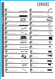
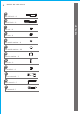
PARTS LIST 3 1 15 Leg post - 2 Small canopy frame - 2 2 16 Leg post - 2 Small canopy frame bar - 1 3 17 Side panel - 2 Cushion - 1 4 18 Long top crossbar - 2 Pillow - 2 5 19 Short top crossbar - 2 Large canopy - 1 6 20 Rear leg crossbar - 1 Small canopy - 1 7 21 Right arm - 1 Net - 1 8 22 Left arm - 1 Throw pillow - 2 9 A Front seat support bar - 1 M6*12 bolt - 4 10 B Rear seat support bar - 1 M6*25 bolt - 2 11 C Seat and back - 1 M6*30 bolt - 4 12 D Hanging b
MODEL NO.
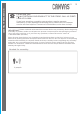
ASSEMBLY PREPARATION 5 Let us help you! DO NOT RETURN YOUR PRODUCT TO THE STORE. CALL US FIRST! 1-888-670-6684 If you have questions regarding your product, require warranty assistance, or have damaged or missing parts, please call our customer service toll-free helpline. Contact us for assistance; we’re here to help. IMPORTANT: Please read and understand this manual before any assembly. Before beginning assembly of product, make sure all parts are present. Compare parts with packaging contents list.
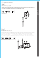
MODEL NO. 088-1682-2 Step 1 Requires 1, 2, A, O. A ASSEMBLY Insert a bolt A through the U-shaped bracket O, and secure into the leg top 1 or 2. Do not tighten. Repeat for the remaining 3 legs. A O Not actual size. O 1 1 Step 2 Requires 1, 2, 3, F, L. Attach the side panel 3 to 2 legs 1 and 2 by inserting a bolt F through a metal washer L, through the hole of the side panel 3, and secure into the leg 2. Make sure the arrow “↑ ↑” is pointing up. Repeat procedure for the other leg 1.
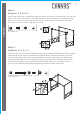
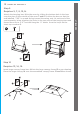
Step 3 Requires 1, 2, 4, E, L. ASSEMBLY Insert two long top crossbars 4 into the holes at the top of each leg. Line up the holes. For each hole insert a bolt E through a metal washer L, through the leg, and secure into the long top crossbar 4. Do not tighten completely. Repeat procedure for the other long top crossbar. E 4 L 1 4 4 Not actual size. 2 1 1 2 4 E Step 4 2 L Requires 4, 5, G, J, L. Attach a short top crossbar 5 onto the long top crossbars 4.
MODEL NO. 088-1682-2 Step 5 Place the rear leg crossbar 6 between the side panels 3. Line up the holes. Insert a bolt D through a metal washer K, through the side panel 3, and secure into the rear leg crossbar 6. Do not tighten completely. Repeat procedure for the other side. Tighten all bolts and nuts from step 1 to step 5 by using the wrenches provided (except bolt A). D K P 3 Q R D Not actual size. 6 K 6 3 Step 6 Requires 7, 8, 9, 10.
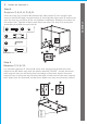
Step 7 Requires 7, 8, 11, H, J, L, M, P, R. ASSEMBLY Unfold the seat and back 11 and lay it on top of the frame. Line up the holes in the arms 7 and 8 with the holes in the side tubes of the seat and back 11. Insert a bolt H (from outside to inside) through the bracket of the arm, through a plastic washer M, through the side bar on the seat and back, through a metal washer L and secure with a nut J. Do not tighten completely. Repeat procedure for the other side. Then securely tighten the bolts and nuts.
MODEL NO. 088-1682-2 Step 9 Attach the hanging bars 12 to the arms by sliding the bottom hole in the bars over the pins on the outside of the arms 7 and 8. Position the bars so that the end labelled “TOP” is up and facing toward the swing seat. At each end of the seat assembly, bring together the holes in the top ends of the hanging bars and thread them on to a “S” hook N. Hang the “S” hooks from the loops on the short top crossbar 5. N 5 N TOP 12 12 7 8 12 8 Step 10 Requires 13, 14, 19.
Step 11 Requires 13, 15. Insert the small canopy frame 15 into the large canopy frame 13 as per drawing. ASSEMBLY 15 15 13 13 15 Step 12 Requires 15, 16, 20, B, K. Insert a bolt B through the metal washer K, through the small canopy frame 15, and into the small canopy frame bar 16. Repeat procedure on the other side. Do not tighten completely. Then insert the small canopy frame 15 into the small canopy 20. K B Not actual size.
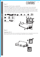
MODEL NO. 088-1682-2 Step 13 Place the assembled canopy top frame on the assembled swing frame. Insert a bolt C through one side of the U shaped bracket O at the top of the leg, through the canopy frame bar 14, through the other side of the U shaped bracket, and secure with a nut I. Do not completely tighten. Repeat procedure for the remaining 3 canopy frame bars 14. Tighten all bolts and nuts from step 1 to step 13 using the wrenches. I I C 14 C 20 P O 19 O Q R Not actual size.
Step 15 Requires 6, 10, 11 ASSEMBLY To convert the swing into a hanging bed, push down the spring ring-pull on rear seat support bar 10 first.Then release the back support tube from the rear seat support bar 10 and fasten it to the U-shaped bracket on the rear leg crossbar 6. When used as a bed, the seat assembly should be secured by these holders and not allowed to swing. 10 10 11 6 10 11 11 10 Step 16 Requires 19, 21. Attach the net 21 to the large canopy 19 by hook-and-loop strip.
MAINTENANCE TECHNICAL SPECIFICATIONS 14 MODEL NO. 088-1682-2 • Though its powder-coated finish is rust-resistant, steel is prone to rust over time with exposure to the elements. In case of rust or scratches, lightly sand the affected area and apply touch-up paint. To maintain the finish, periodically apply wax with a soft cloth. • Wash frames with a mild solution of soap and water; rinse thoroughly. Do not use bleach or solvents.