9I6PEA-L Rev.
Copyright This publication contains information that is protected by copyright. No part of it may be reproduced in any form or by any means or used to make any transformation/adaptation without the prior written permission from the copyright holders. This publication is provided for informational purposes only.
Battery: • Danger of explosion if battery incorrectly replaced. • Replace only with the same or equivalent type recommend by the manufacturer. • Dispose of used batteries according to the battery manufacturer’s instructions. Joystick or MIDI port: • Do not use any joystick or MIDI device that requires more than 10A current at 5V DC. There is a risk of fire for devices that exceed this limit.
FCC and DOC Statement on Class B This equipment has been tested and found to comply with the limits for a Class B digital device, pursuant to Part 15 of the FCC rules. These limits are designed to provide reasonable protection against harmful interference when the equipment is operated in a residential installation.
Table of Contents Chapter 1 - Introduction 1.1 Features and Specifications................................................................................. 7 1.2 Hyper-Threading Technology Functionality Requirements... 14 1.3 Package Checklist........................................................................................................... 15 Chapter 2 - Hardware Installation 2.1 2.2 2.3 2.4 2.5 2.6 System Board Layout ..............................................................................
1 Introduction Chapter 4 - Supported Softwares 4.1 4.2 4.3 4.4 Desktop Management Interface................................................................. Drivers, Utilities and Software Applications................................ 3D Audio Configuration..................................................................................... Installation Notes........................................................................................................
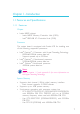
Introduction 1 Chapter 1 - Introduction 1.1 Features and Specifications 1.1.1 Features Chipset • Intel® 865PE chipset - Intel® 865PE Memory Controller Hub (MCH) - Intel® 82801EB I/O Controller Hub (ICH5) Processor The system board is equipped with Socket 478 for installing one of the following supported processors. • Intel® Pentium® 4 Processor with Hyper-Threading Technology - 800MHz/533MHz system data bus - Supports speeds up to 3.
1 Introduction • Suppor ts non-ECC (x64) DIMM using 128Mb, 256Mb or 512Mb • Supports unbuffered DIMMs 64 Mbit Density 128 Mbit 256 Mbit 512 Mbit Density Width X8 X16 X8 X16 X8 X16 X8 X16 Single/Double SS/DS SS/DS SS/DS SS/DS SS/DS SS/DS SS/DS SS/DS 184-pin DDR 64/128MB 32MB/NA 128/256MB 64MB/NA 256/512MB 128MB/NA 512/1024MB 256MB/NA Expansion Slots The system board is equipped with 1 AGP slot and 5 PCI slots. AGP (Accelerated Graphics Port) • Supports AGP 3.
Introduction 1 S/PDIF S/PDIF is a standard audio file transfer format that transfers digital audio signals to a device without having to be converted first to an analog format. This prevents the quality of the audio signal from degrading whenever it is converted to analog. S/PDIF is usually found on digital audio equipment such as a DAT machine or audio processing device.
1 Introduction PCI Bus Master IDE Controller • Two PCI IDE interfaces support up to four IDE devices • Supports ATA/33, ATA/66 and ATA/100 hard drives • PIO Mode 4 Enhanced IDE (data transfer rate up to 14MB/ sec.) • Bus mastering reduces CPU utilization during disk transfer • Supports ATAPI CD-ROM, LS-120 and ZIP IrDA Interface The system board is equipped with an IrDA connector for wireless connectivity between your computer and peripheral devices.
Introduction 1 designed to make inventory, maintenance and troubleshooting of computer systems easier. Refer to chapter 4 for instructions on using the DMI utility. Rear Panel I/O Ports (PC 99 color-coded connectors) • • • • • • • • 2 1 2 1 1 1 1 3 USB 2.0/1.
1 Introduction • Automatic chassis fan and second fan on/off control • Read back capability that displays temperature, voltage and fan speed • Opened chassis alarm Refer to the “PC Health Status” section in chapter 3 and the “Hardware Monitor” section in chapter 4 for more information. 1.1.3 Intelligence Automatic Chassis/Second Fan Off The chassis fan and second fan will automatically turn off once the system enters the Suspend mode.
Introduction 1 Important: The 5VSB power source of your power supply must support ≥720mA. Wake-On-Keyboard/Wake-On-Mouse This function allows you to use the keyboard or PS/2 mouse to power-on the system. Important: The 5VSB power source of your power supply must support ≥720mA. Wake-On-USB Keyboard This function allows you to use a USB keyboard to wake up a system from the S3 (STR - Suspend To RAM) state.
1 Introduction With the Suspend to RAM function enabled, you can power-off the system at once by pressing the power button or selecting “Standby” when you shut down Windows® 98SE/2000/ME/XP without having to go through the sometimes tiresome process of closing files, applications and operating system. This is because the system is capable of storing all programs and data files during the entire operating session into RAM (Random Access Memory) when it powers-off.
Introduction 1 1.2 Hyper-Threading Technology Functionality Requirements Enabling the functionality of Hyper-Threading Technology for your computer system requires ALL of the following platforms.
2 Hardware Installation Chapter 2 - Hardware Installation 2.
Hardware Installation . . . . . . . . 2 Warning: Electrostatic discharge (ESD) can damage your system board, processor, disk drives, add-in boards, and other components. Perform the upgrade instruction procedures described at an ESD workstation only. If such a station is not available, you can provide some ESD protection by wearing an antistatic wrist strap and attaching it to a metal part of the system chassis.
2 Hardware Installation The system board supports the following memory interface. Single Channel (SC) Data will be accessed in chunks of 64 bits (8B) from the memory channels. Virtual Single Channel (VSC) If both channels are populated with different memory configurations, the MCH defaults to Virtual Single Channel. Dual Channel (DC) Dual channel provides better system performance because it doubles the data transfer rate. Single Channel DIMMs are on the same channel.
Hardware Installation 2 The table below lists the various optimal operating modes that should be configured for the memory channel operation.
2 Hardware Installation 2.2.1 Installing the DIM Module A DIM module simply snaps into a DIMM socket on the system board. Pin 1 of the DIM module must correspond with Pin 1 of the socket. Notch Key Tab Tab Pin 1 1. Pull the “tabs” which are at the ends of the socket to the side. 2. Position the DIMM above the socket with the “notch” in the module aligned with the “key” on the socket. 3. Seat the module vertically into the socket. Make sure it is completely seated. The tabs will hold the DIMM in place.
Hardware Installation 2 2.3 CPU 2.3.1 Overview The system board is equipped with a surface mount 478-pin CPU socket. This socket is exclusively designed for installing an Intel processor. 2.3.2 Installing the CPU 1. Locate Socket 478 on the system board. 2. Unlock the socket by pushing the lever sideways, away from the socket, then lifting it up to a 90o angle. Make sure the socket is lifted to at least this angle otherwise the CPU will not fit in properly.
2 Hardware Installation 3. Position the CPU above the socket then align the gold mark on the corner of the CPU (designated as pin 1) with pin 1 of the socket. Important: Handle the CPU by its edges and avoid touching the pins. Gold mark Pin 1 4. Insert the CPU into the socket until it is seated in place. The CPU will fit in only one orientation and can easily be inserted without exerting any force. Important: Do not force the CPU into the socket.
Hardware Installation 2 5. Once the CPU is in place, push down the lever to lock the socket. The lever should click on the side tab to indicate that the CPU is completely secured in the socket. 2.3.3 Installing the Fan and Heat Sink The CPU must be kept cool by using a CPU fan with heatsink. Without sufficient air circulation across the CPU and heat sink, the CPU will overheat damaging both the CPU and system board. Note: • Only use Intel® certified fan and heat sink.
2 Hardware Installation 1. The system board comes with the retention module base already installed. Retention hole Retention hole Retention hole Retention hole Retention module base 2. Position the fan / heat sink and retention mechanism assembly on the CPU, then align and snap the retention legs’ hooks to the retention holes at the 4 corners of the retention module base.
Hardware Installation 2 3. The retention levers at this time remains unlocked as shown in the illustration below. Retention lever Retention lever 4. Move the retention levers to their opposite directions then push them down. This will secure the fan / heat sink and retention mechanism assembly to the retention module base. Note: You will not be able to push the lever down if the direction is incorrect. 5. Connect the CPU fan’s cable connector to the CPU fan connector on the system board.
2 Hardware Installation 2.4 Jumper Settings 2.4.1 Jumper Settings for Clearing CMOS Data JP3 X 1 2 3 1-2 On: Normal (default) 1 2 3 2-3 On: Clear CMOS Data If you encounter the following, a) CMOS data becomes corrupted. b) You forgot the supervisor or user password. c) You are unable to boot-up the computer system because the processor’s ratio/clock was incorrectly set in the BIOS. you can reconfigure the system with the default values stored in the ROM BIOS.
Hardware Installation 2 4. After powering-on the system, press to enter the main menu of the BIOS. 5. Select the CPU Frequency Control submenu and press . 6. Set the “CPU Clock Ratio” or “Clock By Slight Adjust” field to its default setting or an appropriate frequency ratio or bus clock. Refer to the CPU Frequency Control section in chapter 3 for more information. 7. Press to return to the main menu of the BIOS setup utility. Select “Save & Exit Setup” and press . 8.
2 Hardware Installation 2.4.
Hardware Installation 2 These jumpers are used to select the front side bus of the CPU installed on the system board. The default setting is Auto. The system will run according to the front side bus of the CPU installed on the system board. Important: • If you are using a CPU whose frequency has been locked by the manufacturer, overclocking will have no effect. • Overclocking may result to the CPU’s or system’s instability and are not guaranteed to provide better system performance.
2 Hardware Installation 2.
Hardware Installation 2 2.5.1 PS/2 Mouse and PS/2 Keyboard Ports PS/2 Mouse W PS/2 Keyboard The system board is equipped with an onboard PS/2 mouse (Green) and PS/2 keyboard (Purple) ports - both at location CN1 of the system board. The PS/2 mouse port uses IRQ12. If a mouse is not connected to this port, the system will reserve IRQ12 for other expansion cards. . . . . . . . . Warning: Make sure to turn off your computer prior to connecting or disconnecting a mouse or keyboard.
2 Hardware Installation 2.5.2 RJ45 Fast-Ethernet Port RJ45 LAN W The system board is equipped with an onboard RJ45 fast-ethernet LAN port at location CN7 of the system board. It allows the system board to connect to a local area network by means of a network hub. BIOS Setting Enable or disable the onboard LAN in the Integrated Peripherals submenu (“Onboard Device” field) of the BIOS. Refer to chapter 3 for more information.
Hardware Installation 2 2.5.3 Universal Serial Bus Ports W VCC -Data +Data Ground N. C. USB 2 USB 1 10 9 USB 3-4 USB 7-8 USB 5-6 VCC -Data +Data Ground Key X 21 USB 3-8 The system board supports 8 USB 2.0/1.1 ports. USB allows data exchange between your computer and a wide range of simultaneously accessible external Plug and Play peripherals. Two onboard USB 2.0/1.1 ports (Black) are at location CN7 of the system board.
2 Hardware Installation Driver Installation You may need to install the proper drivers in your operating system to use the USB device. Refer to your operating system’s manual or documentation for more information. If you are using a USB 2.0 device, install the “Intel USB 2.0 Drivers” contained in the provided CD. Refer to chapter 4 for more information. Wake-On-USB Keyboard The Wake-On-USB Keyboard function allows you to use a USB keyboard to wake up a system from the S3 (STR - Suspend To RAM) state.
Hardware Installation 2 2.5.4 Serial Ports W COM 1 COM 2 The system board is equipped with onboard serial ports (COM 1: CN6 and COM 2: CN5) - both in Teal/Turquoise color. The serial por ts are RS-232C asynchronous communication por ts with 16C550A-compatible UARTs that can be used with modems, serial printers, remote display terminals, and other serial devices. BIOS Setting Select the serial ports’ I/O address in the Integrated Peripherals submenu (“Super IO Device” field) of the BIOS.
2 Hardware Installation 2.5.5 Parallel Port Parallel W The system board has a standard parallel port (Burgundy) at location CN8 for interfacing your PC to a parallel printer. It supports SPP, ECP, EPP and PntMode. Setting Function SPP (Standard Parallel Port) Allows normal speed operation but in one direction only. ECP (Extended Capabilities Port) Allows parallel port to operate in bidirectional mode and at a speed faster than the SPP’s data transfer rate.
Hardware Installation 2 2.5.6 Game Port Game Port W The Game/MIDI port is identical to that of a standard PC game adapter or game I/O port. Connect an analog joystick to the 15-pin D-sub connector (Gold) at location CN9 of the system board. This port works well with any application that is compatible with the standard PC joystick. BIOS Setting Configure the game port in the Integrated Peripherals submenu (“Super IO Device” field) of the BIOS. Refer to chapter 3 for more information.
2 Hardware Installation 2.5.7 Audio W Center out Center Out Return LFE Out LFE Out Return Key 2 1 9 SL Ground SR Ground Ground/JS Mic Mic Power AuD_R_Out N. C. AuD_L_Out W Surr_con Front audio 10 9 2 1 W GND AuD_Vcc AuD_R_Return Key AuD_L_Return Line-out Mic-in Line-in Audio Jacks The system board is equipped with 3 audio jacks. A jack is a onehole connecting interface for inserting a plug.
Hardware Installation 2 • Line-in Jack (Light Blue - CN3) This jack can be connected to the line-out jack of any external audio devices such as Hi-fi set, CD player, AM/FM radio tuner, synthesizer, etc. Connect a stereo cable from the line-out jack of your external device to this line-in jack. • Mic-in Jack (Pink - CN4) This jack is used to connect an external microphone. Use the CMedia application software to select between using this jack and the front audio’s mic-in jack.
2 Hardware Installation with pin 1 of J4. If you are not using this connector, replace the jumper caps back to their original pin locations. Now install the cardedge bracket to the system chassis. Driver Installation Install the “Audio Drivers” contained in the provided CD. The 3D Audio Configuration software, which is an audio panel for setting basic audio configurations, will at the same time be installed into your system.
Hardware Installation 2 2.6 I/O Connectors 2.6.1 Internal Audio Connectors Ground Ground Left audio Right audio channel channel 1 4W The CD-in (J5) connector is used to receive audio from a CD-ROM drive, TV tuner or MPEG card.
2 Hardware Installation 2.6.2 S/PDIF Connector SPDIF out Key GND VCC SPDIF in 1 5 W The system board is equipped with a S/PDIF connector. One cardedge bracket, mounted with S/PDIF ports, is provided with the system board. Install the card-edge bracket to the system chassis then connect the audio cable connector to J3. Make sure pin 1 of the audio cable connector is aligned with pin 1 of J3.
Hardware Installation 2 2.6.3 Floppy Disk Drive Connector 34 33 X 2 1 The system board is equipped with a shrouded floppy disk drive connector that supports two standard floppy disk drives. To prevent improper floppy cable installation, the shrouded floppy disk header has a keying mechanism. The 34-pin connector on the floppy cable can be placed into the header only if pin 1 of the connector is aligned with pin 1 of the header.
2 Hardware Installation 2.6.4 Serial ATA Connectors 1 7 SATA 2 1 7 SATA 1 GND TXP TXN GND RXN RXP GND X Two Serial ATA cables are provided with the system board. Connect one end of the cable to J18 (SATA 2) or J19 (SATA 1) and the other end to your serial ATA device. BIOS Setting Configure the onboard Serial ATA in the Integrated Peripherals submenu (“OnChip IDE Device” field) of the BIOS. Refer to chapter 3 for more information.
Hardware Installation 2 2.6.5 IDE Disk Drive Connector IDE 1 X 2 1 40 39 2 1 40 39 IDE 2 The system board is equipped with two shrouded PCI IDE headers that will interface four Enhanced IDE (Integrated Drive Electronics) disk drives. To prevent improper IDE cable installation, each shrouded PCI IDE header has a keying mechanism. The 40-pin connector on the IDE cable can be placed into the header only if pin 1 of the connector is aligned with pin 1 of the header.
2 Hardware Installation Note: Refer to your disk drive user’s manual for information about selecting proper drive switch settings. Adding a Second IDE Disk Drive When using two IDE drives, one must be set as the master and the other as the slave. Follow the instructions provided by the drive manufacturer for setting the jumpers and/or switches on the drives. The system board suppor ts Enhanced IDE or ATA-2, ATA/33, ATA/66 or ATA/100 hard drives.
Hardware Installation 2 2.6.6 IrDA Connector IRRX N. C. Ground VCC IRTX 1 5W Connect your IrDA cable to connector J6 on the system board. Note: The sequence of the pin functions on some IrDA cable may be reversed from the pin function defined on the system board. Make sure to connect the cable to the IrDA connector according to their pin functions.
2 Hardware Installation 2.6.7 CPU Fan Connector Power Sense X Ground 1 3 The CPU must be kept cool by using a fan with heatsink. Connect the CPU fan to the 3-pin fan connector at location J13 of the system board. The system is capable of monitoring the speed of the CPU fan. BIOS Setting The “PC Health Status” submenu of the BIOS will display the current speed of the CPU fan. Refer to chapter 3 for more information.
Hardware Installation 2 2.6.8 Chassis Fan and Second Fan Connectors Power Sense X On/Off 1 3 Second fan Power On/Off Sense X1 3 Chassis fan The chassis fan connector (J16) and second fan connector (J15) are used to connect cooling fans. The cooling fans will provide adequate airflow throughout the chassis to prevent overheating the CPU and system board components. The system is capable of monitoring and controlling the speed of these cooling fans.
2 Hardware Installation 2.6.9 Wake-On-LAN Connector Ground +5VSB WOL X1 3 Your LAN card package should include a cable. Connect one end of the cable to the wakeup header on the card and the other end to location J8 on the system board. The network will detect Magic Packet and assert a wakeup signal to power-up the system. Refer to the add-in card’s manual for details. Note: Your LAN card must support the remote wake up function. Important: The 5VSB power source of your power supply must support ≥720mA.
Hardware Installation 2 2.6.10 Chassis Open Alarm Connector Chassis signal Ground 1 2W The system board supports the chassis intrusion detection function. To use this function, connect the chassis intrusion sensor cable from the chassis to J2. Whenever a chassis component has been removed, the sensor sends signal to J2 alerting you of a chassis intrusion event. To disable this function, place a jumper cap over J2.
2 Hardware Installation 2.6.11 LED DIMM Standby Power LED The DIMM Standby Power LED will turn red when the system’s power is on or when it is in the Suspend state (Power On Suspend or Suspend to RAM). It will not light when the system is in the SoftOff state. Important: If the DIMM Standby Power LED is lighted, you must power-off the system then turn off the power supply’s switch or unplug the power cord prior to installing any memory modules.
Hardware Installation 2 2.6.12 Power Connectors 10 20 X +12V 5VSB PW-OK Ground +5V Ground +5V Ground 3.3V 3.3V +5V +5V -5V Ground Ground Ground PS-ON Ground -12V 3.3V 1 11 +12V Ground X 4 3 2 1 Ground +12V We recommend that you use a power supply that complies with the ATX12V Power Supply Design Guide Version 1.1. An ATX12V power supply has a standard 20-pin ATX main power connector and a 4-pin +12V power connector that must be inserted onto CN11 and CN10 connectors respectively.
2 Hardware Installation 2.6.13 Front Panel Connectors SPEAKER J17 RESET HD-LED X 12 90 1 2 PWR-LED ATX-SW HD-LED: Primary/Secondary IDE LED This LED will light when the hard drive is being accessed. RESET: Reset Switch This switch allows you to reboot without having to power off the system thus prolonging the life of the power supply or system. SPEAKER: Speaker Connector This connects to the speaker installed in the system chassis.
Hardware Installation 2 PWR-LED: Power/Standby LED When the system’s power is on, this LED will light. When the system is in the S1 (POS - Power On Suspend) state, it will blink every second. When the system is in the S3 (STR - Suspend To RAM) state, it will blink every second. Note: If a system did not boot-up and the Power/Standby LED did not light after it was powered-on, it may indicate that the CPU or memory module was not installed properly.
3 Award BIOS Setup Utility Chapter 3 - Award BIOS Setup Utility 3.1 The Basic Input/Output System The Basic Input/Output System (BIOS) is a program that takes care of the basic level of communication between the processor and peripherals. In addition, the BIOS also contains codes for various advanced features found in this system board. This chapter explains the Setup Utility for the Award BIOS. After you power up the system, the BIOS message appears on the screen and the memory count begins.
Award BIOS Setup Utility 3 The settings on the screen are for reference only. Your version may not be identical to this one. 3.1.1.1 Date The date format is , , , . Day displays a day, from Sunday to Saturday. Month displays the month, from January to December. Date displays the date, from 1 to 31. Year displays the year, from 1994 to 2079. 3.1.1.2 Time The time format is , , . The time is based on the 24-hour military-time clock. For example, 1 p.m.
3 Award BIOS Setup Utility The settings on the screen are for reference only. Your version may not be identical to this one. IDE HDD Auto Detection Detects the parameters of the drive. The parameters will automatically be shown on the screen. IDE Primary Master/Slave and IDE Secondary Master/Slave The drive type information should be included in the documentation from your hard disk vendor.
Award BIOS Setup Utility 3 Capacity Displays the approximate capacity of the disk drive. Usually the size is slightly greater than the size of a formatted disk given by a disk checking program. Cylinder This field displays the number of cylinders. Head This field displays the number of read/write heads. Precomp This field displays the number of cylinders at which to change the write timing. Landing Zone This field displays the number of cylinders specified as the landing zone for the read/write heads.
3 Award BIOS Setup Utility 3.1.1.5 Video This field selects the type of video adapter used for the primary system monitor. Although secondary monitors are supported, you do not have to select the type. The default setting is EGA/VGA. EGA/VGA CGA 40 CGA 80 Mono Enhanced Graphics Adapter/Video Graphics Array. For EGA, VGA, SVGA and PGA monitor adapters. Color Graphics Adapter. Power up in 40-column mode. Color Graphics Adapter. Power up in 80-column mode. Monochrome adapter.
Award BIOS Setup Utility 3 3.1.1.8 Extended Memory Displays the amount of extended memory detected during boot-up. 3.1.1.9 Total Memory Displays the total memory available in the system.
3 Award BIOS Setup Utility 3.1.2 Advanced BIOS Features The Advanced BIOS Features allows you to configure your system for basic operation. Some entries are defaults required by the system board, while others, if enabled, will improve the performance of your system or let you set some features according to your preference. The screen above list all the fields available in the Advanced BIOS Features submenu, for ease of reference in this manual.
Award BIOS Setup Utility 3 systems like Windows® 98SE/2000/ME/XP or the operating system may not install nor work. 3.1.2.2 CPU L1 & L2 Cache This field speeds up the memory access. 3.1.2.3 Hyper-Threading Technology (for Intel® Pentium® 4 Processor with Hyper-Threading Technology only) This field is used to enable the functionality of the Intel® Pentium® 4 Processor with Hyper-Threading Technology and will appear only when using this processor. 3.1.2.
3 Award BIOS Setup Utility 3.1.2.7 Boot Up Floppy Seek When enabled, the BIOS will check whether the floppy disk drive installed is 40 or 80 tracks. Note that the BIOS cannot distinguish between 720K, 1.2M, 1.44M and 2.88M drive types as they are all 80 tracks. When disabled, the BIOS will not search for the type of floppy disk drive by track number. Note that there will not be any warning message if the drive installed is 360KB. 3.1.2.
Award BIOS Setup Utility 3 3.1.2.12 Security Option This field determines when the system will prompt for the password - everytime the system boots or only when you enter the BIOS setup. Set the password in the Set Supervisor/User Password submenu. System The system will not boot and access to Setup will be denied unless the correct password is entered at the prompt. Setup The system will boot, but access to Setup will be denied unless the correct password is entered at the prompt. 3.1.2.
3 Award BIOS Setup Utility 3.1.2.17 Full Screen Logo Show This field is applicable only if you want a particular logo to appear during system boot-up. Enabled The logo will appear in full screen during system bootup. Disabled The logo will not appear during system boot-up. 3.1.2.18 Small Logo(EPA) Show Enabled The EPA logo will appear during system boot-up. Disabled The EPA logo will not appear during system boot-up.
Award BIOS Setup Utility 3 3.1.3 Advanced Chipset Features The settings on the screen are for reference only. Your version may not be identical to this one. This section gives you functions to configure the system based on the specific features of the chipset. The chipset manages bus speeds and access to system memory resources. These items should not be altered unless necessary. The default settings have been chosen because they provide the best operating conditions for your system.
3 Award BIOS Setup Utility Manual If you want better system performance other than the one “by SPD”, select “Manual”. Then select the best option in the “CAS Latency Time” to “DRAM RAS# Precharge” fields. 3.1.3.2 CAS Latency Time This field is used to select the local memory clock periods. 3.1.3.3 Active to Precharge Delay The options are 5, 6, 7 and 8. 3.1.3.4 DRAM RAS# to CAS# Delay The options are 2, 3 and 4. 3.1.3.5 DRAM RAS# Precharge This field controls RAS# precharge (in local memory clocks). 3.1.
Award BIOS Setup Utility 3 3.1.3.8 Video BIOS Cacheable As with caching the system BIOS, enabling the Video BIOS cache will allow access to video BIOS addresssed at C0000H to C7FFFH to be cached, if the cache controller is also enabled. The larger the range of the Cache RAM, the faster the video performance. 3.1.3.9 Memory Hole At 15M-16M In order to improve system performance, certain space in memory can be reserved for ISA cards. This memory must be mapped into the memory space below 16MB.
3 Award BIOS Setup Utility 3.1.4 Integrated Peripherals The settings on the screen are for reference only. Your version may not be identical to this one. 3.1.4.1 OnChip IDE Device Move the cursor to this field and press . The following screen will appear. The settings on the screen are for reference only. Your version may not be identical to this one.
Award BIOS Setup Utility 3 IDE HDD Block Mode Enabled Disabled The IDE HDD uses the block mode. The system BIOS will check the hard disk drive for the maximum block size the system can transfer. The block size will depend on the type of hard disk drive. The IDE HDD uses the standard mode. On-Chip Primary PCI IDE and On-Chip Secondary PCI IDE These fields allow you to enable or disable the primary and secondary IDE controller. Select Disabled if you want to add a different hard drive controller.
3 Award BIOS Setup Utility On-Chip Serial ATA Setting On-Chip Serial ATA Disabled Auto Manual Disables the onboard serial ATA. The system will automatically detect the serial ATA drives and set them to the available master/slave mode. Select this option to manually configure the serial ATA drives in the “Serial ATA Port0 Mode” and “Serial ATA Port1 Mode” fields. Serial ATA Port0 Mode and Serial ATA Port1 Mode These fields are used to select the master/slave mode of the serial ATA drives.
Award BIOS Setup Utility 3 3.1.4.2 Onboard Device Move the cursor to this field and press . The following screen will appear. The settings on the screen are for reference only. Your version may not be identical to this one. USB Controller All Enabled USB 2.0 Disabled All Disabled Enables all USB ports. USB 2.0 is disabled; USB 1.1 is enabled. Disables all USB ports. USB Keyboard Support If you are using a USB keyboard under DOS, set this field to Enabled.
3 Award BIOS Setup Utility BIOS Flash Protect Enabled This option will protect the system from unnecessary updating or flashing of the BIOS. When enabled, it secures the BIOS therefore any updates to the BIOS will not take effect. Disabled Disables the “BIOS flash lock” function, allowing you to update or flash the BIOS any time needed. Onboard LAN Control This field is used to enable or disable the onboard LAN controller.
Award BIOS Setup Utility 3 3.1.4.3 Super IO Device Move the cursor to this field and press . The following screen will appear. The settings on the screen are for reference only. Your version may not be identical to this one. KBC Input Clock This is used to select the input clock of your keyboard. Onboard FDC Controller Enabled Disabled Enables the onboard floppy disk controller. Disables the onboard floppy disk controller.
3 Award BIOS Setup Utility UART2 Mode Select The system board supports IrDA function for wireless connectivity between your computer and peripheral devices. You may not use IrDA and the COM 2 serial port at the same time. If you are using the COM 2 serial port, make sure this field is set to Normal. To use the IrDA function, follow the steps below. 1. Connect your IrDA cable to connector J6 on the system board. 2.
Award BIOS Setup Utility 3 ECP (Extended Capabilities Port) Allows parallel port to operate in bidirectional mode and at a speed faster than the normal mode’s data transfer rate. EPP (Enhanced Parallel Port) Allows bidirectional parallel port operation at maximum speed. PntMode Allows parallel port to operate in bipolar mode. If you selected EPP, the “EPP Mode Select” field is configurable. If you selected ECP, the “ECP Mode Use DMA” field is configurable.
3 Award BIOS Setup Utility 3.1.5 Power Management Setup The Power Management Setup allows you to configure your system to most effectively save energy. The settings on the screen are for reference only. Your version may not be identical to this one. 3.1.5.1 ACPI Function This function should be enabled only in operating systems that suppor t ACPI. Currently, only Windows ® 98SE/2000/ME/XP supports this function.
Award BIOS Setup Utility 3 3.1.5.3 Power Management This field allows you to select the type (or degree) of power saving by changing the length of idle time that elapses before the HDD Power Down field is activated. Min Saving Max Saving User Define Minimum power saving time for the HDD Power Down = 15 min. Maximum power saving time for the HDD Power Down = 1 min. Allows you to set the power saving time in the “HDD Power Down” field. 3.1.5.
3 Award BIOS Setup Utility 3.1.5.8 Soft-Off by PWR-BTTN This field allows you to select the method of powering off your system. Delay 4 Sec. Regardless of whether the Power Management function is enabled or disabled, if the power button is pushed and released in less than 4 sec, the system enters the Suspend mode. The purpose of this function is to prevent the system from powering off in case you accidentally “hit” or pushed the power button. Push and release again in less than 4 sec to restore.
Award BIOS Setup Utility 3 3.1.5.10 PM Wake Up Events Move the cursor to this field and press . The following screen will appear. The settings on the screen are for reference only. Your version may not be identical to this one. Resume on PCI Event Enabled Disabled This field should be set to Enabled only if your PCI card such as LAN card or modem card uses the PCI PME (Power Management Event) signal to remotely wake up the system.
3 Award BIOS Setup Utility Resume On LAN If you are using a LAN card that supports the remote wake up function, set this field to Enabled. The will allow the network to remotely wake up a Soft Power Down (Soft-Off) PC. However, if your system is in the Suspend mode, you can wake up the system only through an IRQ or DMA interrupt. Refer to “Wake-On-LAN Connector” in chapter 2 for more information.
Award BIOS Setup Utility 3 Time (hh:mm:ss) Alarm This is used to set the time you would like the system to power-on. If you want the system to power-on everyday as set in the “Date (of Month) Alarm” field, the time set in this field must be later than the time of the RTC set in the Standard CMOS Features submenu. Keyboard/Mouse Power On This field allows you to use the keyboard or PS/2 mouse to poweron the system. Disabled Default setting. Uses the power button to power on the system.
3 Award BIOS Setup Utility KB Power On Hot Key This field is used to select a function key that you would like to use to power-on the system.
Award BIOS Setup Utility 3 3.1.6 PnP/PCI Configurations This section describes configuring the PCI bus system. It covers some very technical items and it is strongly recommended that only experienced users should make any changes to the default settings. The settings on the screen are for reference only. Your version may not be identical to this one. 3.1.6.1 Reset Configuration Data Enabled The BIOS will reset the Extended System Configuration Data (ESCD) once automatically.
3 Award BIOS Setup Utility 3.1.6.3 IRQ Resources This field is used to set each system interrupt to either “PCI Device” or “Reserved”. 3.1.6.4 PCI/VGA Palette Snoop This field determines whether the MPEG ISA/VESA VGA cards can work with PCI/VGA or not. Enabled MPEG ISA/VESA VGA cards work with PCI/VGA. Disabled MPEG ISA/VESA VGA cards does not work with PCI/ VGA. 3.1.6.5 PCI IRQ Assignment By default, an IRQ is automatically assigned to the PCI devices that are installed in the PCI slots.
Award BIOS Setup Utility 3 3.1.7 PC Health Status The settings on the screen are for reference only. Your version may not be identical to this one. 3.1.7.1 Current System Temperature, Current CPU Temperature, Current Chassis Fan Speed, Current CPU Fan Speed and Current Second Fan Speed These fields show the internal temperature of the system, current temperature of the CPU and the current fan speed of the chassis, CPU and second fans in RPM (Revolutions Per Minute). 3.1.7.
3 Award BIOS Setup Utility 3.1.7.4 Shutdown Temperature You can prevent the system from overheating by selecting a temperature in this field. If the system detected that its temperature exceeded the one set in this field, it will automatically shutdown. This function will work only when you enable this function in the Hardware Monitor utility.
Award BIOS Setup Utility 3 3.1.8 CPU Frequency Control The settings on the screen are for reference only. Your version may not be identical to this one. 3.1.8.1 CPU Clock Ratio This field is used to select the frequency ratio of the processor. Important: The frequency ratio of some processors may have been locked by the manufacturer. If you are using this kind of processor, setting an extended ratio for the processor will have no effect. The system will instead use its factory default ratio. 3.1.8.
3 Award BIOS Setup Utility 3.1.8.4 Clock By Slight Adjust This field provides several options for selecting the external system bus clock of the processor. The available options allow you to adjust the processor’s bus clock by 1MHz increment. Important: Selecting an external bus clock other than the default setting may result to the processor’s or system’s instability and are not guaranteed to provide better system performance.
Award BIOS Setup Utility 3 3.1.8.6 CPU Vcore Adjust This field allows you to manually select higher core voltage supplied to the CPU. If you wish to use the CPU’s default core voltage, leave this field in its default setting, which is “Default”. The CPU’s Vcore will be generated according to the CPU VID configuration. Important: Although this function is supported, we do not recommend that you use a higher voltage because unstable current may be supplied to the system board causing damage. 3.1.8.
3 Award BIOS Setup Utility 3.1.9 Load Fail-Safe Defaults The “Load Fail-Safe Defaults” option loads the troubleshooting default values permanently stored in the ROM chips. These settings are not optimal and turn off all high performance features. You should use these values only if you have hardware problems. Highlight this option in the main menu and press . If you want to proceed, type and press . The default settings will be loaded.
Award BIOS Setup Utility 3 3.1.10 Load Optimized Defaults The “Load Optimized Defaults” option loads optimized settings from the BIOS ROM. Use the default values as standard values for your system. Highlight this option in the main menu and press . Type and press to load the Setup default values.
3 Award BIOS Setup Utility 3.1.11 Set Supervisor Password If you want to protect your system and setup from unauthorized entry, set a supervisor’s password with the “System” option selected in the Advanced BIOS Features. If you want to protect access to setup only, but not your system, set a supervisor’s password with the “Setup” option selected in the Advanced BIOS Features. You will not be prompted for a password when you cold boot the system.
Award BIOS Setup Utility 3 3.1.12 Set User Password If you want another user to have access only to your system but not to setup, set a user’s password with the “System” option selected in the Advanced BIOS Features. If you want a user to enter a password when trying to access setup, set a user’s password with the “Setup” option selected in the Advanced BIOS Features. Using user’s password to enter Setup allows a user to access only “Set User Password” that appears in the main menu screen.
3 Award BIOS Setup Utility 3.1.13 Save & Exit Setup When all the changes have been made, highlight “Save & Exit Setup” and press . Type “Y” and press . The modifications you have made will be written into the CMOS memory, and the system will reboot. You will once again see the initial diagnostics on the screen. If you wish to make additional changes to the setup, press simultaneously or after memory testing is done.
Award BIOS Setup Utility 3 3.1.14 Exit Without Saving When you do not want to save the changes you have made, highlight “Exit Without Saving” and press . Type “Y” and press . The system will reboot and you will once again see the initial diagnostics on the screen. If you wish to make any changes to the setup, press simultaneously or after memory testing is done.
3 Award BIOS Setup Utility 3.2 Updating the BIOS To update the BIOS, you will need the new BIOS file and a flash utility, AWDFLASH.EXE. Please contact technical support or your sales representative for the files. 1. Save the new BIOS file along with the flash utility AWDFLASH.EXE to a floppy disk. 2. Reboot the system and enter the Award BIOS Setup Utility to set the first boot drive to “Floppy”. 3. Save the setting and reboot the system. 4.
Award BIOS Setup Utility 3 6. The following will appear. Do You Want to Save BIOS (Y/N) This question refers to the current existing BIOS in your system. We recommend that you save the current BIOS and its flash utility; just in case you need to reinstall the BIOS. To save the current BIOS, press then enter the file name of the current BIOS. Otherwise, press . 7. The following will then appear. Press “Y” to Program or “N” to Exit 8. Press to flash the new BIOS.
4 Supported Software Chapter 4 - Supported Software 4.1 Desktop Management Interface (DMI) The system board comes with a DMI built into the BIOS. DMI, along with the appropriately networked software, is designed to make inventory, maintenance and troubleshooting of computer systems easier. With DMI, a network administrator or MIS engineer can remotely access some information about a particular computer system without physically going to it.
Supported Software 4 4.1.
4 Supported Software Add DMI 1. Use the ← or → arrow keys to select the Add DMI menu. 2. Highlight the item on the left screen that you would like to add by using the ↑ or ↓ arrow keys, then press . 3. The cursor will move to the screen you select allowing you to enter information about the added item. 4. Press to save information into the flash ROM. To view information about the added items, go to the Edit DMI menu. Load DMI File 1. Use the ← or → arrow keys to select the Load DMI File menu.
Supported Software 4 4.2 Drivers, Utilities and Software Applications The CD that came with the system board contains drivers, utilities and software applications required to enhance the performance of the system board. Inser t the CD into a CD-ROM drive. The autorun screen (Mainboard Utility CD) will appear.
4 Supported Software 4.2.1 Intel Chipset Software Installation Utility The Intel Chipset Software Installation Utility is used for updating Windows 98/98SE/2000/ME/XP's INF files so that the Intel chipset can be recognized and configured properly in the system. To install the utility, please follow the steps below. 1. On the left side of the autorun screen, click the “CHIPSET” icon. 2. Click “Intel Chipset Software Installation Utility” on the main menu. The following screen will appear. 3.
Supported Software 4 4.2.2 Audio Drivers The audio drivers are supported in the following operating systems: Windows 98, Windows 98 SE, Windows ME, Windows NT 4.0, Windows 2000 and Windows XP. To install the driver, please follow the steps below. 1. On the left side of the autorun screen, click the “AUDIO” icon. 2. Click “Audio Drivers” on the main menu. The following screen will appear. Click “Install Device Driver”.
4 Supported Software 3. The following screen will appear. 4. Follow the prompts on the screen to complete installation. 5. Reboot the system for the driver to take effect. Note: The 3D Audio Configuration software, which is an audio panel for setting basic audio configurations, will at the same time be installed into your system. Refer to the “3D Audio Configuration” section in this chapter for more information.
Supported Software 4 4.2.3 Intel USB 2.0 Drivers If you are using a USB 2.0 device, you must install the USB 2.0 driver. The drivers are supported in the following operating systems: Windows 98 SE, Windows ME and Windows 2000. To install the driver, please follow the steps below. 1. On the left side of the autorun screen, click the “USB” icon. 2. Click “Intel USB 2.0 Drivers” on the main menu. If you are using Windows 98 SE or Windows ME, the following screen will appear.
4 Supported Software Windows 2000 does not support auto-installation of the USB 2.0 driver. When you click “Intel USB 2.0 Drivers”, the “readme” screen will appear. 3. Follow the installation instructions shown on the screen. 4. Reboot the system for the driver to take effect. Important: If you are using Windows® XP, you must install the Windows Service Pack 1 USB 2.0 driver which comes available after you have installed the operating system.
Supported Software 4 4.2.4 LAN Drivers The LAN drivers suppor t autorun for the following operating systems: Windows 98, Windows 98 SE, Windows ME, Windows 2000 and Windows XP. To install the driver, please follow the steps below. 1. On the left side of the autorun screen, click the “NETWORK” icon. 2. Click “LAN Drivers” on the main menu. The following screen will appear. 3. Follow the prompts on the screen to complete installation. 4. Reboot the system for the driver to take effect.
4 Supported Software 4.2.5 Hardware Monitor The system board comes with the Hardware Monitor utility contained in the provided CD. This utility is capable of monitoring the system’s “health” conditions and allows you to manually set a range (Highest and Lowest Limit) to the items being monitored. If the settings/values are over or under the set range, a warning message will pop-up. The utility can also be configured so that a beeping alarm will sound whenever an error occurs.
Supported Software 4 4.2.6 McAfee VirusScan Online (English OS only) The McAfee VirusScan Online is the most reliable and convenient way of protecting your PC from computer viruses. When you install McAfee VirusScan Online, your computer is safe because it automatically scans for viruses and checks for virus updates so that PC protection stays up-to-date. To install, please follow the steps below. 1. On the left side of the autorun screen, click the “TOOLS” icon. 2.
4 Supported Software 4.2.7 Microsoft DirectX 9 To install, please follow the steps below. 1. On the left side of the autorun screen, click the “TOOLS” icon. 2. Click “Microsoft DirectX 9” on the main menu. The following screen will appear. 3. Click “Yes” to continue. 4. Follow the prompts on the screen to complete installation. 5. Reboot the system for the driver to take effect.
Supported Software 4 4.3 3D Audio Configuration When you install the audio driver, the 3D Audio Configuration software will at the same time be installed into your system. 3D Audio Configuration is an audio panel for setting basic audio configurations. It allows you to configure 2-channel, 4-channel and 6channel audio modes as well as configure the audio effects.
4 Supported Software Speaker Output When you open 3D Audio Configuration, the default screen that appears is the Speaker Output. This is where you will configure analog output settings to speakers. S/PDIF This panel is used to configure S/PDIF output which provides a lowdistor tion digital data transfer between audio devices. Volume Control This panel provides digital volume control for all 6 channels. You can regulate each volume to the speaker when playing digital sound sources.
Supported Software 4 Microphone This panel is used to configure the microphone. Xear 3D X Xear 3D is a sound technology for 2-channel virtual surround, adjustable multi-channel sound field, innovative listening mode, amazing sound effects and 3D positional audio. It has 3 functional blocks: Virtual Speaker Shifter, Sound Effect and Multi-channel Music Demo. A complete version of the 3D Audio Configuration manual is provided in the CD.
4 Supported Software 4.4 Installation Notes 1. "Autorun" ONLY supports the Windows 98 SE, Windows ME, Windows 2000, Windows NT 4.0 and Windows XP operating systems. If after inserting the CD, "Autorun" did not automatically start (which is, the Main Board Utility CD screen did not appear), please go directly to the root directory of the CD and double-click "Setup". 2.
Enabling Hyper-Threading Technology A Appendix A - Enabling Hyper-Threading Technology A.1 Enabling Hyper-Threading Technology To enable the functionality of the Hyper-Threading Technology, please follow the requirements and steps below. Basically, the following presumes that you have already installed an Intel® Pentium® 4 Processor with Hyper-Threading Technology. 1. The system requires a minimum of 300 Watt ATX 12V power supply. 2.
A Enabling Hyper-Threading Technology c. Click the General tab. The processor shown under Computer should resemble the one shown below. d. Now click the Hardware tab then click Device Manager. The items shown under Computer and Processors should resemble the ones shown below.
Enabling Hyper-Threading Technology A e. Lastly, press the and keys simultaneously. The Windows Task Manager dialog box will appear. Click the Performance tab. The diagram under CPU Usage History should resemble the one shown below.
B System Error Message Appendix B - System Error Message When the BIOS encounters an error that requires the user to correct something, either a beep code will sound or a message will be displayed in a box in the middle of the screen and the message, PRESS F1 TO CONTINUE, CTRL-ALT-ESC or DEL TO ENTER SETUP, will be shown in the information box at the bottom. Enter Setup to correct the error. B.1 POST Beep There are two kinds of beep codes in the BIOS.
System Error Message B setting than indicated in Setup. Determine which setting is correct, either turn off the system and change the jumper or enter Setup and change the VIDEO selection. FLOPPY DISK(S) fail (80) Unable to reset floppy subsystem. FLOPPY DISK(S) fail (40) Floppy type mismatch. Hard Disk(s) fail (80) HDD reset failed. Hard Disk(s) fail (40) HDD controller diagnostics failed. Hard Disk(s) fail (20) HDD initialization error. Hard Disk(s) fail (10) Unable to recalibrate fixed disk.
C Troubleshooting Appendix C - Troubleshooting C.1 Troubleshooting Checklist This chapter of the manual is designed to help you with problems that you may encounter with your personal computer. To efficiently troubleshoot your system, treat each problem individually. This is to ensure an accurate diagnosis of the problem in case a problem has multiple causes. Some of the most common things to check when you encounter problems while using your system are listed below. 1.
Troubleshooting C The picture seems to be constantly moving. 1. The monitor has lost its vertical sync. Adjust the monitor’s vertical sync. 2. Move away any objects, such as another monitor or fan, that may be creating a magnetic field around the display. 3. Make sure your video card’s output frequencies are supported by this monitor. The screen seems to be constantly wavering. 1. If the monitor is close to another monitor, the adjacent monitor may need to be turned off.
C Troubleshooting Hard Drive Hard disk failure. 1. Make sure the correct drive type for the hard disk drive has been entered in the BIOS. 2. If the system is configured with two hard drives, make sure the bootable (first) hard drive is configured as Master and the second hard drive is configured as Slave. The master hard drive must have an active/bootable partition. Excessively long formatting period. 1.
Troubleshooting C Serial Port The serial device (modem, printer) doesn’t output anything or is outputting garbled characters. 1. Make sure that the serial device’s power is turned on and that the device is on-line. 2. Verify that the device is plugged into the correct serial port on the rear of the computer. 3. Verify that the attached serial device works by attaching it to a serial port that is working and configured correctly.