
User`s guide

EE PRO for TI - 89, 92 Plus
Equations - Linear Amplifiers
109
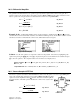
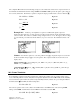
-PQYP8CTKCDNGU
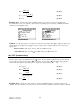
βTDAMΩTGAΩ4$#AMΩ4NAMΩ4UAMΩ
%QORWVGF4GUWNVU#K4KP'AΩ4QAMΩ
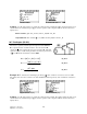
28.8 Darlington (CC-CE)
The Darlington configuration connected as a common collector-common emitter
configuration is described in this section. The first two equations define the input
resistance Rin and output resistance Ro, in terms of base resistance rb, emitter
resistance re, collector resistance rrc, and current gain
ββ
0. The final equation
calculates the voltage gain Av, in terms of the emitter and load resistances, the
source impedance, and the current gain
ββ
0.
Rin rb re
=+⋅
β
0
Eq. 28.8.1
Ro
rrc
=
β
0
Eq. 28.8.2
Av
Rl
re
Rs
=
−
+
β
0
2
Eq. 28.8.3
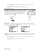
Example 28.8 -
An amplifier circuit has a base, emitter, and load resistance of 1.5 kΩ, 25 Ω, and 10 kΩ,
respectively. The configuration has a value of
ββ
0 equal to 100. The source and collector resistances are 1 kΩ and
100 kΩ. Find the voltage gain, input and output resistances.
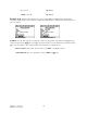
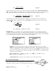
Upper Screen Display Lower Screen Display
Solution -
Use all of the equations to compute the solution for this problem. Press „ to display the input screen,
enter all the known variables and press „ to solve the equations. The computed results are shown in the screen
displays above.
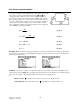
-PQYP8CTKCDNGU
ββ
TDAMΩTTEAMΩTGAΩ4NAMΩ4UAMΩ
%QORWVGF4GUWNVU#X4KPAΩ4QAMΩ