
User`s guide


EE Pro for TI-89, 92 Plus
Analysis - Filter Design
25
Chapter 6 Filter Design
This chapter covers a description of the software under the heading Filter Design. Three filter designs are included
in this section. Design computations result in the value of component elements comprising the filter.
v Chebyshev Filter
v Butterworth Filter
v Active Filter
6.1 Chebyshev Filters
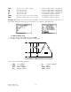
This section of the software computes component values for Chebyshev filters between equal terminations. Inputs
are termination resistance, pass band characteristics, attenuation at some out-of-band frequency, and allowable
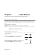
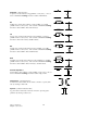
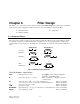
passband ripple as shown in Fig. 6.1. The Chebyshev circuit elements are assumed to be ideal, and are illustrated
below.
Odd Elements Even Elements
Low Pass
Cn
Ln
High Pass
Ln
Cn
Band Pass
Lpn
Cpn
Lsn Csn
Band
Elimination
Lsn Csn
Lpn
Cpn
Fig. 6.1 Chebyshev Filter Elements
Field Descriptions - Input Screen
Char: (Bandpass Characteristic) Press ¸ to select Low Pass, High Pass,
Band Pass, or Band Elimination.
R: (Termination Resistance in ohms) Enter a real number, or algebraic expression
of defined terms.
f0: (Cutoff Frequency in Hz - for Low Pass and High Pass) Enter a real number.
(Center Frequency in Hz - for Band Pass and Band Elimination) Enter a real number.
f1: (Attenuation Frequency in Hz) Enter a real number.
∆dB: (Attenuation in dB) Enter a real number.
Bandwidth: (Bandwidth in Hz - only appears for Band Pass or Band Elimination) Enter a real number.
Ripple: (Pass Band Ripple in dB) Enter a real number.