Gas Cooker with Double Oven Model: C 5210 GB Instruction Manual
Thank you for buying your new CAPLE Gas Cooker. To ensure that you get the best results from your new CAPLE Gas Cooker, we strongly suggest that you read this instruction manual thoroughly before use. This manual contains installation advice, usage instructions and a cleaning guide, as well as other important facts about your CAPLE Gas Cooker. If treated with care, your CAPLE Gas Cooker should give you years of trouble-free cooking.
Safety Reminders Instruction Book DO NOT line the oven, grids, trays etc. with aluminium foil as this could adversely affect the heating elements and it could also damage the interior surfaces. This appliance should only be used for it’s intended purpose as described in these instructions. Ensure that you fully understand these instructions before operating this appliance. the oven. Space Requirements Faults Ensure that the specified ventilation space around the appliance is not obstructed.
Electrical Requirements IMPORTANT: The appliance must be installed in accordance with the manufacturer’s instructions. Incorrect installation, for which the manufacturer accepts no responsibility, may cause damage to persons, animals and things. N.B. For connection to the mains, do not use adapters, reducers or branching devices as they can cause overheating and burning. If the installation requires alterations to the domestic electrical system call an expert.
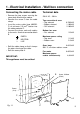
1 - Electrical Installation - Wall box connection Connecting the mains cable Technical data – Remove the two screws securing the cover plate A behind the cooker. – Remove the screw C from the cable clamp. – Insert the mains cable (type H05RRF) of minimum 2,5 mm2 section into the cable protector P. – Connect the phase and earth cables to the mains terminal connection block B. 230 V AC - 50 Hz N L Top conventional oven – Top element – Bottom element – Grill element EARTH NEUTRAL LIVE 0.700 kW 1.
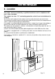
FOR THE INSTALLER 2 - Location The cooker must be installed by a qualified technician and in compliance with local safety standards. 450 mm 650 mm This cookers has class “2/1” overheating protection so that it can be installed next to a cabinet. The furniture walls adjacent to the cooker must be made of material resistant to heat. The veneered syntetical material and the glue used must be resistant to a temperature of 120°C in order to avoid ungluing or deformations.
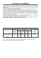
Provision for ventilation The room containing the cooker should have an air supply in accordance with BS.5540: Part 2: 1989. All rooms require an openable window or equivalent while some rooms require a permanent vent in addition to the openable window. The cooker should not be installed in a bed-sitting room, of volume less than 21 m3.
3 - Gas connection Gas installation Important note This appliance is supplied for use on NATURAL GAS only and cannot be used on any other gas without modification. This appliance is manufactured for conversion to LPG if required and is supplied with a conversion kit. The cooker must be installed by a qualified person in accordance with the Gas Safety (Installation and Use) (Amendment) Regulation 1990 and the relevant building/l.E.E. Regulations.
The installation of the cooker to Natural Gas or LP Gas must be carried out by a qualified gas engineer. Installer shall take due account of the provisions of the relevant British Standards Code of Practice, the Gas Safety Regulations and the Building Standards (Scotland) (Consolidation) Regulations issued by the Scottish Development Department. Installation to Natural Gas Installation to Natural Gas must conform to the Code of Practice, etc. The supply pressure for Natural Gas is 20 mbar.
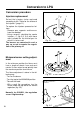
Conversion to LPG Conversion procedure Injectors replacement J Select the injectors to be replaced according to the “Table for the choice of the injectors” (page 11). To replace the injectors proceed as follows: - Remove pan supports and burners from the cooktop. - Using a wrench, substitute the nozzle injectors “J” (fig. 3.3, 3.4) with those most suitable for the kind of gas for which it is to be used. The burners are conceived in such a way so as not to require the regulation of the primary air. Fig.
TABLE FOR THE CHOICE OF THE INJECTORS Cat: II 2H3+ G 30 - 28-30 mbar G 31 - 37 mbar Nominal Power Reduced Power [kW] [kW] By-pass [1/100 mm] Ø injector Auxiliary (A) 1,00 0,30 27 50 Semi-rapid (SR) 1,75 0,45 32 65 Triple-ring 3,50 1,50 65 95 BURNERS [1/100 mm] G 20 20 mbar By-pass [1/100 mm] Ø injector adjustable GB 72 (X) [1/100 mm] 97 (Z) 135 (T) INCREASE OF AIR NECESSARY FOR GAS COMBUSTION (2 m3/h x kW) BURNERS Air necessary for combustion [m3/h] Auxiliary (A) 2,00 Sem
4 - Features and Technical Data Cooking hob 2 2 1 3 1. Auxiliary burner (A) 1,00 kW 2. Semi-rapid burner (SR) - 1,75 kW 3. Triple ring burner (TC) - 3,50 kW Fig. 4.1 Fig. 1.1 Fig. 4.2 12 11 8 6 5 4 3 2 1 Control panel Pilot lamps: Controls description 11. Conventional oven temperature light 12. Main oven temperature light 1. 2. 3. 4. 5. 6.
How To Use the Hob Burners Hob burners Each hob burner is controlled by a separate gas tap operated by a control knob (fig. 4.3) which has 3 positions marked on the knob, these are: – Symbol ● : tap closed (burner off) – Symbol : High (maximum) – Symbol : Low (minimum) Push in and turn the knob anti-clockwise to the selected position. Low High Fig. 4.3 To turn the burner off, fully rotate the knob clockwise to the off position: ●.
Choice of burner The burner must be chosen according to the diameter of the pans and energy required. Burners Pan diameter Auxiliary Semi-rapid Triple-ring 12 ÷ 14 cm 16 ÷ 24 cm 26 ÷ 28 cm do not use pans with concave or convex bases Fig. 4.4 Saucepans with handles which are excessively heavy, in relationship to the weight of the pan, are safer as they are less likely to tip. Pans which are positioned centrally on burners are more stable than those which are offset.
Correct use of triple-ring burner The flat-bottomed pans are to be placed directly onto the pan-support. When using a WOK you need to place the supplied stand in the burner to avoid any faulty operation of the triple-ring burner (Fig. 4.5 - 4.6). CORRECT WRONG Fig. 4.5 Fig. 4.
5 - How To Use the Top Conventional oven Attention: the oven door becomes very hot during operation. Keep children away. WARNING: The door is hot, use the handle. General features Operating principles As the name implies, this oven features a number of special characteristics from the functional point of view.
Thermostat knob (Fig. 5.2) Rotate the knob clockwise to set the oven for one of the functions described. Function selector knob (Fig. 5.1) This only sets the cooking temperature but does not switch the oven on. Rotate clockwise until the required temperature is reached (from 50 to 225 °C). The light above the function selector will illuminate when the oven is swiched on and turns off when the oven reaches the correct temperature.
6 - How To Use the Bottom Main oven Attention: the oven door becomes very hot during operation. Keep children away. Switch and thermostat selector (Fig. 6.1) Turn the selector knob (fig. 6.1) to the required function. o Off The oven light is switched on. The fan operates without the heating element, this function can be used for defrosting. 50-250 The oven light is switched on. The oven temperature can be set between 50°C 250°C.
Cooking with air forced Fan cooking is more economical and quicker than cooking in a conventional oven. The moving hot air surrounds the food and penetrates it more quickly than in a conventional oven. The oven can be filled with different dishes all requiring the same cooking temperature. Subtract 10 minutes per hour for every dish requiring a cooking time of more than 1 hour and reduce the heat by 10-20°C; the hotter the oven, the more the temperature can be reduced.
Recommended cooking temperature Food °C °F Gas Mark Shelf Position* Cooking Time (approx) CAKES Victoria sandwich Small cakes/buns Maidera cake Fruit cake Rich fruit cake Scones 190 190 180 170 150 225 375 375 350 325 300 425 5 5 4 3 2 8-9 2 or 3 1 and 2 2 or 3 3 3 or 4 2 20-25 mins 15-20 mins 20 mins 13/4 hours 21/2 hours 8-10 mins PASTRY Puff Short crust Plate tarts Quiches and flans 225 200 200-210 200-210 425 400 400-410 400-410 8-9 6 6 6 2 2 1 or 2 1 or 2 10-20 mins 20-30 mins 30-35 mi
7 - Electronic clock / end cooking timer The electronic programmer is a device with the following functions: – 24 hours clock with illuminated display – Timing of oven cooking with automatic switch-off (max. 99 minutes). Electronic clock Upon immediate connection of the oven or after a mains failure, three zeros will flash on the programmer panel. To set the clock it is necessary to push the button and then, within 7 seconds, the or button until you have set the correct time.
8 - Cleaning and Maintenance General advice – Important: Before any operation of cleaning and maintenance disconnect the appliance from the electrical network. – It is advisable to clean when the appliance is cold. – When the appliance is not being used, it is advisable to keep the gas tap closed.
Cleaning Inside of oven All the enamelled parts must be cleaned with a sponge and soapy water or other non-abrasive products. Dry preferably with a soft cloth. Acidic substances like lemon juice, tomato sauce, vinegar etc. can damage the enamel if left too long. This must be cleaned regularly. Remove and refit the side runner frames as described on the next chapter. With the oven warm, wipe the inside walls with a cloth soaked in very hot soapy water or another suitable product.
Burners They can be removed and washed only with soapy water. Detergents can be used but must not be abrasive or corrosive. Do not use abrasive sponges or pads. Do not put in dishwasher. After each cleaning, make sure that the burner-caps, as well as the burners, have been well wiped off and CORRECTLY POSITIONED. It is essential to check that the burner flame distributor “F” and the cap “C” has been correctly positioned (see fig. 8.1) failure to do so can cause serious problems.
B A Fig. 8.2 Fig. 8.3 Triple ring burner The triple ring burner must be correctly positioned (see figs. 8.2 - 8.3); the burner rib must be enter in their logement as shown by the arrow. The burner correctly positioned must not rotate (fig. 8.3). Then position the cap A and the ring B (fig. 8.3 8.4). Fig. 8.4 Fig. 8.
Using the top and the main oven for the first time You are advised to carry out the following operations: – Clean the inside of the two ovens with a cloth soaked in water and neutral detergent and dry thoroughly. – Hang up the wire racks on the oven walls (Figure 8.6 and 8.7). Fig. 8.6 – Slide in, on the guides, the shelf and the tray etc. (Figure 8.8). The shelf must be fitted so that the safety catch, which stops it sliding out, faces the inside of the oven.
Fig. 8.10A Type A Removing the oven door The oven door can easily be removed as follows: – Open the door to the full extent (fig. 8.10A). – Attach the retaining rings to the hooks on the left and right hinges (fig. 8.10B). Fig. 8.10B – Hold the door as shown in fig. 8.10. – Gently close the door and withdraw the lower hinge pins from their location (fig. 8.10C). – Withdraw the upper hinge pins from their location (fig. 8.10D). – Rest the door on a soft surface.
Type B Dismontling the door Please operate as follows: L – Open the door completely. – Push down the lever “L” and, keeping it in this position, slowly close the door in order to block the hinge. – Grip the door (as indicated in fig. 8.12) and, while closing it, release the two hinges as shown in fig. 8.13. Fig. 8.11 Door assenbly – Grip the door with your hands placed near the hinges and raise the levers “H” with your forefingers (fig. 8.
Helpful Advice Trouble shooting Problem Food too brown but not cooked. Remedy Turn down the oven temperature slightly and cook a little longer Problem Food cooked but not brown enough. Remedy Increase temperature. Problem Food baking unevenly. Remedy 1. The temperature may be slightly high turn it down 2. Position the food in the centre of the shelves rather than towards the sides of tho oven. 3. Rotate the food a half turn in the oven. 4. Try pre-heating the oven for 5-15 minutes prior to baking.
IMPORTANT: Ovens get hot. Keep children away from this appliance at all times. If Your Oven Does Not Work Before calling a CAPLE service engineer run through the following checklist. 1. The cooker is connected to the power supply and that the fuse is intact. 2. Make sure the timer control is set to the manual position, and that the oven has not been set inadvertently for an automatic or timed programme. If you are in any doubt about carrying out these checks, call the CAPLE Helpline on 0870 241 1142.
CAPLE “Built-in” Service Should you require service at any time, please contact the Caple Helpline on 0870 241 1142. Caple have a nationwide service network of engineers who will respond quickly to your call. Always replace spare parts with genuine Caple spares. These are available from authorised Caple Service Centres or by mail order from our National Service Stores, simply telephone 0870 241 1142. When ordering parts always quote the model number and serial number of your appliance.