
Specifications

SG-231 MANUAL
SGC Inc. SGC Building, 13737 S.E. 26th St. Bellevue, WA. 98005 USA
© 11/00 SGC, Inc.
P.O. Box 3526, 98009 Fax: (425) 746-6384 Tel: (425) 746-6310
E-Mail: sgc@sgcworld.com Website: www.sgcworld.com
31
5.5 Antenna Coupler Mounting
The coupler is mounted using the proper mounting holes on the base plate. Choose a
location immediately adjacent to the antenna feed point. In trunk-mounted mobile
installations, locate the coupler so that the antenna insulator is within a few centimeters
of the antenna exit hole. Note also that the antenna lead must pass through an
insulated bushing. High voltage connecting cable must be used. (RG-8U cable with
solid insulation may be used if the outer shielding is removed). When the coupler is
installed on the outside, or on the deck, we recommend a protective housing.
5.6 Antenna Connection
The antenna lead is connected to the high voltage screw. During operation, use two
wrenches when tightening the nut to prevent the stud rotating. A potential of several
thousand volts may be present at the antenna terminal and adequate protection must be
made against accidental contact. It is also necessary that the antenna be spaced at least
3 centimeters from the conducting surface. Sharp points in the lead-in wire should be
avoided to prevent corona discharges.
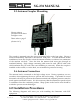
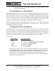
6.0 Installation Procedures
The following diagrams will assist you with installing the Smartuner with SGC
equipment.
Shown without
protection from direct
sunlight or rain.
Please refer to page 5
(Section 1.6.3)