
Specifications

SG-231 MANUAL
SGC Inc. SGC Building, 13737 S.E. 26th St. Bellevue, WA. 98005 USA
© 11/00 SGC, Inc.
P.O. Box 3526, 98009 Fax: (425) 746-6384 Tel: (425) 746-6310
E-Mail: sgc@sgcworld.com Website: www.sgcworld.com
34
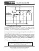
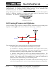
SmartLock Pro Schematic Diagram
C5
.1u
R2
220
1/2W
12 VDC
Hold
Reset
Tuned
Rx Amp
C4
.1u
SW3
SPDT
D1
1N751A
R4
1M
JP1
SW2
PUSHBUTTON
R3
330
R1
150
DS1
Green LED
SW1
4PDT
C2
.1u
DS2
Red LED
C3
.1u
C1
.1u
C6
.1u
GND
No Tune/Reset
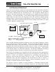
6.5 Weatherdeck Mounting
Weatherdeck mounting can be used. Years of experience have shown that inside
mounting or even splash-proof mounting is preferred, particularly in cold, damp
environments. In tropical use, shielding from direct sunlight is desirable.
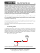
The base of the antenna should be connected to the high voltage feed-through screw on
the housing. Note that this screw is not designed to support heavy mechanical loads. If
such loading is encountered, use a strain relief.
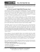
The ground system should be connected to the 1/4-inch stainless steel stud protruding
from the bottom of the housing. Connection to the ground system is extremely
important to a successful installation. Ground runs of over a few inches should be
made from 4-inch-wide copper strap or larger. The actual ground system should be as
good as possible, as the ground is an integral part of the antenna system. See section 5.3
on grounding. However, couplers in general require the antenna parameters to be
within the range of the tuning parameters or the coupler will not find a satisfactory
match. The computer in the SG-231 cannot second-guess the installer.
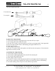
A proper antenna/ground installation is of great
importance: regardless of whether your station is a base
station, marine, or land mobile.