
Specifications

SG-231 MANUAL
SGC Inc. SGC Building, 13737 S.E. 26th St. Bellevue, WA. 98005 USA
© 11/00 SGC, Inc.
P.O. Box 3526, 98009 Fax: (425) 746-6384 Tel: (425) 746-6310
E-Mail: sgc@sgcworld.com Website: www.sgcworld.com
40
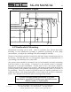
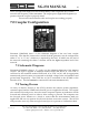
7.6 Central Processing Unit
A tune-up algorithm, which is contained in the memory of the microprocessor, actually
implements the antenna matching. It is designed around the MC 68HC711E9 CPU that
features a versatile instruction set, RAM, and EEPROM (memory which is saved after
the coupler is turned off). The antenna coupler relays are controlled by latches U8, U6,
and U7, which receive serial data input directly from the CPU.
During operation, data is transferred into the CPU from the A to D ports and Input
Capture port (measures RF frequency). Basically, the program monitors the status of
the input sensors and—starting from a preset condition—uses a built-in algorithm to
achieve a tuned condition. When the tuning algorithm is complete, the CPU saves the
settings in its EEPROM, which is addressed by the applied RF frequency.
This non-volatile memory table is the basis of the exclusive learning feature of the SG-
231. After it has stored and latched the network status, the CPU waits for RF to cease
transmitting and returns to the Stop mode. When RF is re-transmitted, the first step in
the tuning algorithm is to measure the frequency of the signal passing through the
coupler. From the frequency data, the computer then searchers its EEPROM for
previously stored data. If data is found, it is tested for validity, and the required “end
of tune” conditions will be sensed by the RF sensors. Then the data will be latched in
place, and the CPU will again wait for RF to cease transmitting and return to the Stop
mode. This process takes about 20 milliseconds, which is the same length of time that is
required to close the network relays.
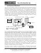
7.7 Initialization
The microcomputer is usually in the Stop mode and requires an interrupt signal (XIRQ)
to start program implementation. The XIRQ is obtained from the RF detector circuitry.
This line, going low, will wake the CPU from the Stop mode.
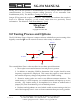
7.8 Bypass Operation, Jumpers
The SG-231 may be bypassed for broadband (un-tuned antenna) scanning listening. All
you need to do is press the reset button of the SmartLock PRO (if installed) or turn
power to the coupler off and on. When the coupler comes back on, the tuning elements
remain out of the circuit until the Smartuner is activated by a transmitted signal.
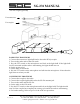
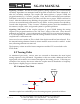
If broadband operation is required during receive for scan operation, jumper JP1 may
be set to the Yes position. This will drop the tuning elements out of the circuit on
receive only. Jumper JP1 is located adjacent to shield along the edge of the printed
circuit board. If you open your Smartuner to access this jumper, please use caution to
ensure that the waterproof seal is carefully placed prior to refitting the coupler cover.