
Specifications

SG-231 MANUAL
SGC Inc. SGC Building, 13737 S.E. 26th St. Bellevue, WA. 98005 USA
© 11/00 SGC, Inc.
P.O. Box 3526, 98009 Fax: (425) 746-6384 Tel: (425) 746-6310
E-Mail: sgc@sgcworld.com Website: www.sgcworld.com
42
5. The BITE (Built-In-Test-Equipment) Indicator Tune LED includes a safety
feature that alerts the operator to a mismatched condition, with blinking
indicators, when proper tuning conditions have not been met. In this situation,
the software will “time out” within 20 seconds unless a new frequency is
sensed, which will cause an immediate time out, and the coupler will attempt
to match the new frequency.
The microprocessor of the coupler “wakes up” every time the coupler has for-ward
power. However, re-tuning takes place only if the frequency has changed or the VSWR
exceeds 2:1.
8.1 Program Description
When DC power is applied, the computer initializes the processor registers in
accordance with the hardware. All tuning elements are then removed and the 'tune'
indicators are turned off. At this time the computer reverts to a "sleep" mode awaiting
RF power.
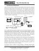
Detecting no forward power. When RF power is detected, the CPU will perform a test
to verify forward power is present. If no forward power is detected, the computer will
revert to the Stop mode. If forward power is detected, the CPU next checks the Hold
signal from the SmartLock. If the user has switched on the Tuned Lock function of the
SmartLock Pro, the Hold line will be low and the CPU will not proceed with the tuning
algorithm. It will wait for forward power to be shut off and return to Stop mode.
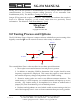
Detecting forward power. Once forward power is detected and the SmartLock Pro is
switched to Normal, the current coupler settings are sent to the relays. Next, the VSWR
is checked and the frequency is measured. If the VSWR is greater than 2:1 or a
difference in frequency is detected, the program branches to the re-tune program. If it
is determined that the VSWR is less than 2:1 and the frequency has not changed, the
computer returns to the Stop mode.
Re-tuning. Once it is determined that re-tuning is necessary, a test is made to see if JP2
is set to tune from memory. If the result is re-tuning from memory, settings are recalled
from the EEPROM based on the frequency measured.
The recalled data is then tested for validity. If the data proves invalid, it is bypassed
and re-tuning is performed. If the data recalled proves valid, the data is sent to the
relays and the VSWR is checked. If the VSWR is less than 2:1, the program branches to
the “OK Tuned” section of the program. If the VSWR is found to be greater than 2:1,
the program branches to the “re-tune” program.
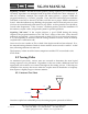
Selecting tuning path. Several tests are made to determine which tuning algorithm or
path should be used to tune the coupler. These tests are based on frequency, antenna
input impedance, antenna phase, and VSWR. Numerous sub-routines are executed
repeatedly, depending on the status of the criteria mentioned above, in order to achieve
proper tuning.