
Specifications


SG-231 MANUAL
SGC Inc. SGC Building, 13737 S.E. 26th St. Bellevue, WA. 98005 USA
© 11/00 SGC, Inc.
P.O. Box 3526, 98009 Fax: (425) 746-6384 Tel: (425) 746-6310
E-Mail: sgc@sgcworld.com Website: www.sgcworld.com
44
1. Series inductance is added until the phase is deemed as being inductive. At
this point it is normal for the input impedance to be low.
2. Input capacitance is added until the antenna is no longer inductive.
3. The program will continue to increment the series inductance in .125 µH
steps—each time normalizing the input impedance with input capacitance until
a low VSWR is measured of less than 2:1. This process will continue until the
VSWR has climbed back to higher than 2:1 or the impedance has become high.
4. The settings that gave the lowest VSWR have been kept in memory and are
now recalled to verify it is a low VSWR
5. At this point the tune indicators are engaged. The current relay data is
saved if JP2 is set to tune from memory; if JP1 is set to the tune elements out
during receive position, the program waits until forward power is no longer
present, then removes all tuning elements. The frequency is saved for future
frequency comparison, and the computer reverts to the Stop mode.
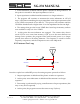
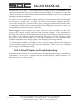
8.2.2 Antenna Too Long
C
L1
Antenna
out
50 ohms
Once the coupler has verified RF power, the tuning sequence proceeds as follows:
1. Output capacitance is added until the phases switches to capacitive.
2. At this point, series inductance is added until the antenna is no longer
capacitive.
3. Fine tuning is performed by trying a small amount of input capacitance (this
may or may not be required).
4. At this point, the program executes the same as step 5 (above).