
Specifications


SG-231 MANUAL
SGC Inc. SGC Building, 13737 S.E. 26th St. Bellevue, WA. 98005 USA
© 11/00 SGC, Inc.
P.O. Box 3526, 98009 Fax: (425) 746-6384 Tel: (425) 746-6310
E-Mail: sgc@sgcworld.com Website: www.sgcworld.com
48
Improper bonding. The fourth kind of ground fault you may encounter occurs where
the ground is not properly bonded to the coupler. We go to considerable effort to make
sure the stainless steel ground stud is well connected to the coupler.
Particularly in automobiles and aircraft, a single ground connection will not do. It is
mandatory that at least two ground bolt connections are used.
Inaccurate assumptions. The fifth situation to check for is what we call “dangerous
assumptions” about the ground system. When you bond from the antenna coupler to
copper or iron water pipes, you might make an assumption that the water pipes are a
good ground. But in many installations, copper pipes are used in the building but a
plastic main connects to the municipal system just outside the service entrance. So
much for a good ground.
10.2 Antenna Faults
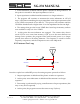
The key to getting the most out of your Smartuner is to realize the antenna begins right
at the high voltage screw on the SG-231 case. In other words, this is the feed point of
your antenna system. Failing to install your coupler accordingly will result in
unsatisfactory operation. With this concept in mind, you can easily avoid some of the
common troubles with a properly planned installation.
Coaxial cable on output. Coax on the output is probably the single most commonly
asked question about the coupler and is the most misunderstood. Let us reiterate: The
Smartuner was not designed to feed a piece of coax.
Stray ground capacitance. Stray ground capacitance is the next largest cause of
malfunctioning installations. If you have a long lead wire from the coupler to a feed-
through (on a wall or bulkhead), you significantly increase your chance of problems.
Wire running parallel to a grounded surface may represent a significant capacitance to
ground and, just as with coax, this will cause problems.
To give you an idea how these two points can cause problems, let us relate an incident
that happened in late 1992. A Smartuner user had a coupler installed in a mobile ham
radio installation. The coupler could not find a lock on several bands. After going
through his installation carefully, the user called SGC for technical support. This user
was nearing wit’s end.
In working through the logical troubleshooting process with him, we discovered that he
had used coaxial feed line from the insulator on the coupler to the antenna feed point.
Because he had read about the dangers of capacitance to ground in an earlier edition of
this manual, he did not have the coax shield grounded. We had him remove the
ungrounded braid and the installation worked fine.
Experiences like this have taught us to be fanatical about using the shortest possible
wire and no coax on the output of the coupler.