Twin Oven Gas Cooker Model: CR 9210 GB Instruction Manual
Thank you for buying your new CAPLE cooker. To ensure that you get the best results from your new CAPLE cooker, we strongly suggest that you read this instruction manual thoroughly before use. This manual contains installation advice, cleaning tips and a cooking guide, as well as other important facts about your CAPLE cooker. If treated with care, your CAPLE appliance should give you years of trouble-free cooking.
Safety Reminders Instruction Book This appliance should only be used for it’s intended purpose as described in these instructions. Ensure that you fully understand these instructions before operating this appliance. DO NOT line the oven, grids, trays etc. with aluminium foil as this could adversely affect the heating elements and it could also damage the interior surfaces. Do not place baking trays or the drip tray on the base of the oven chamber.
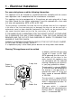
1 - Electrical Installation For your safety please read the following information: This appliance must be installed by a qualified technician according with the current local regulations and in compliance with the manufacturer instructions. This appliance has to be equipped with a 13 amp three pin mains plug with a 3 amp fuse fitted. Should the fuse require replacement, it must be replaced with a fuse rated at 3 amp and approved by ASTA or BSI to BS 1362.
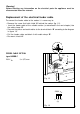
Warning! Before effecting any intervention on the electrical parts the appliance must be disconnected from the network. Replacement of the electrical feeder cable To connect the feeder cable to the cooker it is necessary to: – Remove the screw that hold shield “A” behind the cooker (fig. 1.2). – Insert the feeder cable of the suitable section (as described in the next chapter) into the cable clamp “D”. – Connect the phase and earth cables to the terminal block “B” according to the diagram in figure 1.3.
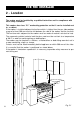
FOR THE INSTALLER 2 - Location The cooker must be installed by a qualified technician and in compliance with local safety standards. 450 mm 650 mm This cookers has class “2/1” overheating protection so that it can be installed next to a cabinet. If the cooker is installed adjacent to furniture which is higher than the gas hob cooktop, a gap of at least 200 mm must be left between the side of the cooker and the furniture.
Backguard Before installing the cooker, assemble the backguard “C” (fig. 2.2). 1. 2. 3. 4. The backguard “C” can be found packed at the rear of the cooker. Before assembling remove any protective film/adhesive tape. Remove the two spacers “A” and the screw “B” from the rear of the cooktop. Assemble the backguard as shown in figure 2.2 and fix it by screwing the central screw “B” and the spacers “A”. C B A Fig. 2.
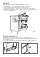
WARNING When raising cooker to upright position always ensure two people carry out this manoeuvre to prevent damage to the adjustable feet (fig. 2.5). WARNING Be carefull: do not lift the cooker by the door handle when raising to the upright position (fig. 2.6). WARNING When moving cooker to its final position DO NOT DRAG (fig. 2.7). Lift feet clear of floor (fig. 2.5). Fig. 2.5 Levellig the cooker The cooker may be levelled by screwing the lower ends of the feet IN or OUT (fig. 2.8). Fig. 2.6 8 Fig. 2.
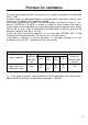
Provison for ventilation The room containing the cooker should have an air supply in accordance with BS.5540: Part 2: 1989. All rooms require an openable window or equivalent while some rooms require a permanent vent in addition to the openable window. The cooker should not be installed in a bed-sitting room, of volume less than 21 m3.
3 - Gas connection Gas installation Gas connection Important note The installation of the cooker to Natural Gas or LP Gas must be carried out by a qualified gas engineer. Installers shall take due account of the provisions of the relevant British Standards Code of Practice, the Gas Safety Regulations and the Building Standards (Scotland) (Consolidation) Regulations issued by the Scottish Development Department.
Gas connection The gas supply must be connected to the gas inlet which is located at the left or the right hand rear of the appliance (fig. 3.1). The pipe does not cross the cooker. When screwing the connecting tube operate with two spanners (fig. 3.2). The unused end inlet pipe must be closed with the plug, interposing the gasket. After connecting to the mains, check that the coupling are correctly sealed, using soapy solution, but never a flame. Fig. 3.2 Plug Fig. 3.
Conversion to LPG Conversion procedure Injectors replacement J Select the injectors to be replaced according to the “Table for the choice of the injectors” (page 13). Injectors obtained Service. not supplied can be from the After-Sales To replace the injectors proceed as follows: - Remove pan supports and burners from the cooktop. - Using a wrench, substitute the nozzle injectors “J” (fig. 3.3, 3.4) with those most suitable for the kind of gas for which it is to be used.
TABLE FOR THE CHOICE OF THE INJECTORS Cat: II 2H3+ GB BURNERS Nominal Power Reduced Power [kW] [kW] G 20 20 mbar G 30 - 28-30 mbar G 31 - 37 mbar By-pass [1/100 mm] [1/100 mm] [mm] By-pass Ø injector Tube ring opening [1/100 mm] [1/100 mm] [mm] ring Ø injector Tube opening 1,00 0,30 27 50 - 72 (X) - Semi-rapid (SR) 1,75 0,45 32 65 - 97 (Z) - Rapid (R) 3,00 0,75 42 85 - 115 (Y) - Triple-ring 3,50 1,50 65 95 - 135 (T) - Left Oven 3,70 0,75 42 92 fully open Lef
LEFT OVEN Oven burner and grill burner replacement of injectors a) oven burner Fig. 3.6 – Lift and remove the lower panel inside the oven. – Remove the burner securing screw (fig. 3.6). – Withdraw the burner as shown in figure 3.7 and rest it inside the oven. Take care not to damage the wire to the ignition electrode and the safety valve probe. Fig. 3.7 – Using a 7 mm box spanner, unscrew the injector (indicated by the arrow in fig. 3.7) and replace it by the proper one according to the kind of gas.
Regulation of air supply to oven and grill burners Using a cross-head screwdriver, slacken the screw securing the air flow regulation collar (fig. 3.10 and 3.11) and move the collar forward or backward to increase or reduce the air aperture in accordance with gas type and the indications in the “TABLE FOR THE CHOICE OF THE INJECTORS”. Light the burner and check the flame. Fig. 3.11 Ring opening Fig. 3.
RIGHT OVEN Oven burner and grill burner replacement of injectors a) oven burner – Lift and remove the lower panel inside the oven. Fig. 3.12 – Remove the 2 burner securing screws (fig. 3.12). – Withdraw the burner as shown in figure 3.13 and rest it inside the oven. Take care not to damage the wire to the ignition electrode and the safety valve probe. – Using a 7 mm box spanner, unscrew the injector (indicated by the arrow in fig. 3.13) and replace it by the proper one according to the kind of gas.
Regulation of air supply to oven and grill burners Using a screwdriver, slacken the screw securing the air flow regulation collar (fig. 3.16 and 3.17) and rotate the collar clockwise or anti-clockwise to increase or reduce the air aperture in accordance with gas type and the indications in the “TABLE FOR THE CHOICE OF THE INJECTORS”. Light the burner and check the flame. Fig. 3.17 Ring opening Fig. 3.
LEFT and RIGHT OVENS G Regulating of the oven minimum To be effected only for the oven burner (as the grill burner has an only fixed input) operating on the thermostat as follows: – Light the oven taking the knob to Max. position. – remove the knob and by a thin screwdriver (3 mm section - 100 mm long) unscrew of about a half turn the screw by-pass G, passing through the front panel hole (fig. 3.
4 - Features and Technical Data 2 3 4 1 2 1 Fig. 4.1 Cooking hob - (Fig. 4.1) 1. 2. 3. 4.
Control Panel Fig. 4.2 1 2 Control panel 1. 2. 3. 4. 5. 6. 7. 8. 9. 10. 11. 20 3 4 5 6 7 (Fig. 4.
How To Use the Hob Burners Hob burners Each hob burner is controlled by a separate gas tap operated by a control knob (fig. 4.3) which has 3 positions marked on the knob, these are: – Symbol ● : tap closed (burner off) – Symbol : High (maximum) – Symbol : Low (minimum) Push in and turn the knob anti-clockwise to the selected position. Low High Fig. 4.3 To turn the burner off, fully rotate the knob clockwise to the off position: ●.
Choice of burner The burner must be chosen according to the diameter of the pans and energy required. Fig. 4.4 Burners Pan diameter Auxiliary Semi-rapid Rapid Triple-ring Wok 12 ÷ 14 cm 16 ÷ 24 cm 24 ÷ 26 cm 26 ÷ 28 cm max 36 cm do not use pans with concave or convex bases Saucepans with handles which are excessively heavy, in relationship to the weight of the pan, are safer as they are less likely to tip. Pans which are positioned centrally on burners are more stable than those which are offset.
Correct use of triple-ring burner The flat-bottomed pans are to be placed directly onto the pan-support. To use the WOK you need to place the proper stand in order to avoid any faulty operation of the triple-ring burner (Fig. 4.5 - 4.6). IMPORTANT: The special grille for wok pans (fig. 4.6) MUST BE PLACED ONLY over the pan-rest for the triple-ring burner. WRONG Fig. 4.5 CORRECT Fig. 4.
5 - Minute counter Minute counter The minute counter is a timed acoustic warning device which can be set for a maximum of 60 minutes. The knob (Fig. 5.1) must be rotated clockwise as far as the 60 minute position and then set to the required time by rotating it anticlockwise. 24 Fig. 5.
6 - How To Use the “Left Gas Oven” Attention: the oven door becomes very hot during operation. Keep children away. General features The oven is furnished completely clean; it is advisable, however, upon first use, to turn the oven on to the maximum temperature (position ) to eliminate possible traces of grease from the oven burner. The same operation should be followed for grill burner. Oven thermostat The oven thermostat (fig. 6.
Ignition of the oven burner 1) Open the oven door to the full extent. WARNING: Risk of explosion! The oven door must be open during this operation. 2) Lightly press and turn the thermostat knob anti-clockwise to max position ( fig. 6.3). 3) Press the knob firmly until the burner lights. Never continue this operation for more than 15 seconds. If the burner has still not ignited, wait for about 1 minute prior to repeating the ignition.
Ignition of the grill burner Very important: the grill must always be used with the oven door ajar and with shield "A” mounted. Attention: the oven door becomes very hot during operation. Keep children away. 1) Open the oven door to the full extent. WARNING: Risk of explosion! The oven door must be open during this operation. 2) Lightly press and turn the thermostat knob clockwise to the , position (fig. 6.4). 3) Press the knob firmly until the burner lights.
Use of the grill Very important: the grill must always be used with the oven door slightly open and with shield "A” mounted (Fig. 6.6). Mount shield “A” which serves to protect the control panel from the heat. Turn on the grill, as explained in the preceding paragraphs and let the oven preheat for about 5 minutes with the door ajar. Introduce the food to be cooked, positioning the rack as close to the grill as possible. The dripping pan should be placed under the rack to catch the cooking juices and fats.
7 - How To Use the “Right Gas Oven” Attention: the oven door becomes very hot during operation. Keep children away. General features The oven is furnished completely clean; it is advisable, however, upon first use, to turn the oven on to the maximum temperature (position ) to eliminate possible traces of grease from the oven burner. The same operation should be followed for grill burner. Oven thermostat The oven thermostat (fig. 7.
Ignition of the oven burner Oven cooking 1) Open the oven door to the full extent. WARNING: Risk of explosion! The oven door must be open during this operation. 2) Lightly press and turn the thermostat knob anti-clockwise to max position ( fig. 7.3). 3) Press the knob firmly until the burner lights. Never continue this operation for more than 15 seconds. If the burner has still not ignited, wait for about 1 minute prior to repeating the ignition.
Ignition of the grill burner Very important: the grill must always be used with the oven door ajar and with shield "A” mounted. Attention: the oven door becomes very hot during operation. Keep children away. The grill burner generates the infra-red rays for grilling. To light the grill burner operate as follow: 1) Open the oven door. WARNING: Risk of explosion! The oven door must be open during this operation. 2) Lightly press and turn the thermostat knob clockwise to the position (fig. 7.4).
Note: It is recommended that you do not grill for longer than 30 minutes at any one time. Attention: the oven door becomes very hot during operation. Keep children away. H O T Very important: the grill must always be used with the oven door slightly open and with shield "A” mounted (Fig. 7.6). Mount shield “A” which serves to protect the control panel from the heat. Turn on the grill, as explained in the preceding paragraphs and let the oven preheat for about 5 minutes with the door ajar.
Rotisserie This is used for spit roasting under the grill and comprises: – an electric motor fitted to the rear of the oven – a stainless steel skewer provided with slide-out heatless handgrip and two sets of adjustable forks – a skewer support to be fitted in the middle runner. The rotisserie motor is operated by a switch knob (Fig. 7.8 position). Fig. 7.8 Use of the rotisserie Very important: the rotisserie must always be used with the oven door ajar and with shield “A” mounted (Fig. 7.6).
8 - Recommended cooking temperature Food °C °F Shelf Position* Cooking Time (approx) CAKES Victoria sandwich Small cakes/buns Maidera cake Fruit cake Rich fruit cake Scones 190 190 180 170 150 225 375 375 350 325 300 425 2 or 3 1 and 2 2 or 3 3 3 or 4 2 20-25 mins 15-20 mins 20 mins 13/4 hours 21/2 hours 8-10 mins PASTRY Puff Short crust Plate tarts Quiches and flans 225 200 200-210 200-210 425 400 400-410 400-410 2 2 1 or 2 1 or 2 10-20 20-30 30-35 40-45 225 220 230 425 425 450 2 1 or 2 2
9 - Cleaning and Maintenance General advice – When the appliance is not being used, it is advisable to keep the gas tap closed. – Every now and then check to make sure that the flexible tube that connects the gas line or the gas cylinder to the appliance is in perfect condition and eventually substitute it if it shows signs of wearing or damage. – The periodical lubrication of the gas taps must be done only by specialized personnel. – If a tap becomes stiff, do not force; contact your local Service Centre.
Cleaning All the enamelled parts must be cleaned with a sponge and soapy water or other nonabrasive products. Dry preferably with a soft cloth. Acidic substances like lemon juice, tomato sauce, vinegar etc. can damage the enamel if left too long. Stainless steel surfaces The stainless steel front panels on this cooker (facia, oven door, storage compartment) are protected by a finger-print proof lacquer.
Burners They can be removed and washed only with soapy water. Detergents can be used but must not be abrasive or corrosive. Do not use abrasive sponges or pads. Do not put in dishwasher. After each cleaning, make sure that the burner-caps, as well as the burners, have been well wiped off and CORRECTLY POSITIONED. It is essential to check that the burner flame distributor “F” and the cap “C” has been correctly positioned (see fig. 9.1-9.2) - failure to do so can cause serious problems.
Triple ring burner The triple ring burner must be correctly positioned (see fig. 9.5); the burner rib must be enter in their logement as shown by the arrow see fig. 9.3). Then position the cap A and the ring B (fig. 9.4 - 9.5). The burner correctly positioned must not rotate (fig. 9.4). Fig. 9.3 A B Fig. 9.4 38 Fig. 9.
Fig. 9.6 Fig. 9.7 Oven door Storage compartment The internal glass panel can be easily removed for cleaning by unscrewing the retaining screws (Fig. 9.6) The storage compartment is accessible through the pivoting panel (fig. 9.7). Do not store flammable material in the oven or in the storage compartment.
Replacing the oven light bulb Assembly and dismantling of the side runner frames Switch the cooker off at the mains. When the oven is cool unscrew and replace the bulb with another one resistant to high temperatures (300°C), voltage 230 V (50 Hz), 15 W, E14. Note: Oven bulb replacement is not covered by your guarantee. – Fit the side runner frames into the holes on the side walls inside the oven (Fig. 9.8). – Slide the tray and rack into the runners (Fig. 9.9).
Removing the oven door Fig. 9.10A The oven door can easily be removed as follows: – Open the door to the full extent (fig. 9.10A). – Attach the retaining rings to the hooks on the left and right hinges (fig. 9.10B). – Hold the door as shown in fig. 9.10. – Gently close the door and withdraw Fig. 9.10B the lower hinge pins from their location (fig. 9.10C). – Withdraw the upper hinge pins from their location (fig. 9.10D). – Rest the door on a soft surface.
Helpful Advice Trouble shooting If the oven light falls: Problem Food too brown but not cooked. 1. Before carrying out any work on the electrical parts of the appliance, the appliance must first be disconnected from the electrical supply. 2. When the oven is cool, reach back and upwards inside the oven, the bulb is in the top corner. 3. Unscrew the light glass cover, replace the bulb with a new one of the same specification and screw the cover back until it is hand tight.
CAPLE “Built-in” Service Should you require service at any time, please contact the Caple Helpline on 0870 241 1142. Caple have a nationwide service network of engineers who will respond quickly to your call. Always replace spare parts with genuine Caple spares. These are available from authorised Caple Service Centres or by mail order from our National Service Stores, simply telephone 0870 241 1142. When ordering parts always quote the model number and serial number of your appliance.