CR1001SS Range Cooker INSTRUCTIONS - & Recommendations for use, installation & maintenance of this appliance Dir.
THIS MANUAL CONTAINS: • • • • User’s instructions Cooking guide Installation instructions Servicing instructions Appliance conformity – The appliance complies with European Directives EEC 89/336, 92/31 and 93/68 relative to electromagnetic compatibility. – All our appliances are designed and constructed in compliance with European standards EN 60 335-1 and EN 60 335-2-6 and their subsequent amendments, in conformance with the requirements of the European Low Voltage Directive EEC 73/23 and 93/68.
Contents CHARACTERISTICS ........................................................................................................................................................................................ P. 5 INSTRUCTION FOR USE ............................................................................................................................................................................... P. 6 TIMER FUNCTION .............................................................................
Characteristics DIMENSIONS OF THE COOKERS COOKER DIMENSIONS AND CHARACTERISTICS TWIN 100X60 Height of top a1= 90±1 cm Depth C1= 60 cm Width B= 100 cm Height to top of splashback a2= 96±1 cm Depth with over door open C2= 94 cm Working capacity litres left 57 right 33,5 Class Combined and electric cooker type Ec type examination certificate n. Ec type examination fig.
Instructions for use Twin model ovens and grills The standard conformation consists of a multifunction oven on the left and a static oven on the right. The left oven is equipped with grill with an energy regulator. The right oven is equipped with a fixed grill (with turnspit). Runners The shelves slot into the runners “A” .These runners (see Fig. 6) mean that dishes can be cooked at different heights, 10 for twin model, selecting the best height for the particular dish.To remove the shelves see fig. 6.
Cooling fan Your cooker is fitted with a fan to cool the control panel, the oven doors and the oven door handles.It switches on automatically when the temperature reaches a certain level. The green light on the control panel shows that the fan is operating. The fan stops automatically at the end of cooking when the temperature of the appliance has dropped to a sufficiently safe level. MULTIFUNCTION OVEN - Allows different types of food to be cooked on more than one shelf.
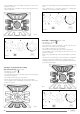
Setting 1 - conventional cooking (static oven) (fig. 10 - 10/A) - Turn knob (1) symbol . - Knob (3) (grill energy regulator) to zero - The heating elements are in operation. - The red light confirms they are in operation. - Turn the thermostat knob (2) to the chosen temperature. - The yellow light comes on. - Wait for the yellow light to go out before placing the foods in the oven. - This cooking mode is suitable for biscuits, cakes, bread and roasts. fig. 11 fig. 10 fig.
Setting 5 - fan grilling (gentle grilling) (fig. 14 - 14/A) - Turn knob (1) to symbol - Turn knob (3) to 6. - The grill element and the fan on the back of the oven are ope-rating. - The red light confirms they are in operation. - Turn the thermostat knob (2) to the chosen temperature. - The yellow light comes on and will go out when the chosen temperature is reached. - Arrange the foods on the grill grid and place it so that the foods are about 5 cm below the element.
- The yellow light comes on and will go out when the chosen temperature is reached. - This cooking mode is suitable for cakes in general and for warming serving dishes. - Wait for the yellow light to go out before placing the foods in the oven. - This cooking mode is especially suitable for cooking large amounts of food, such as roasts, turkey, etc. fig. 16/A fig. 15 Setting 8 - rapid grilling (fig. 17 - 17/A) - Turn knob (1) to symbol - Turn knob (3) to 6.
Timer function Electronic cooker programmer COOKING DURATION button and adjust how long you wish the oven to cook with the +/- buttons. Then set the time you wish cooking to END by pressing the END TIME button and adjusting the time with the +/- buttons. Turn the Temperature and Function knobs to the desired positions. The symbol “A” will appear on the screen. When the oven turns an a cooking pot symbol will also appear on the screen.
Griddle plate (not supplied - optional extra) Panset use Before using for the first time: wipe the surface of the griddle plate with oil and heat so that the oil evaporates (repeat after each use). Place the griddle plate on the central burner. Pre-heat for 5 minutes. The control knob can be turned to a lower position. Using a pan set in a right-hand oven For cooking operations requiring the use of the oven shelf, the tray provided should be placed in the runners beneath the shelf, as shown in fig.
Cooking guide OVEN COOKING CHART The oven control setting and cooking times given below are intended to be used only as a guide. Individual taste may require the temperature to be altered to provide a preferred result. For best results preheat the oven until the yellow light goes out. fig.
Cooker Servicing GENERAL RULES All servicing operations described in this section must be carried out by qualified personnel only. Before starting any servicing operations on a cooker, it must be unplugged or switched off at the mains supply. If work is to be carried out on the electrical or gas components underneath the hob (e.g. switches, thermostat taps, etc.) follow the order shown in Fig. 22. fig.
fig. 26 fig. 27 fig. 27/A fig. 28 REPLACEMENT OF THE TAPS When replacing a tap, follow the instructions below: - Remove the knobs by pulling - Remove the hob and the control panel following the sequence of instructions in Fig. 22 - 23 - 24. Take the burners apart as shown in Fig. 29. - Remove the ignition switch “B” (Fig. 29) - if fitted - after removing clip “A” - Unscrew the lock nuts “C” from the junction ramp between the burner (Fig.
REPLACEMENT OF THE BURNERS AND SWITCHES - To replace these accessories, remove the hob following the sequence of instructions in Fig. 22 - 23 - 24 - To take the burners apart follow the sequence of instructions in Fig. 31-32. 1) unscrew the lock nuts “C” and “D” and screws “E” (Fig. 31) 2) with the burner free turn and unscrew screws “F”. REPLACEMENT OR FITTING OF POWER SUPPLY CABLE Follow the advice below: (see Fig.
Technical notice for installer TECHNICAL NOTICE FOR INSTALLER IMPORTANT The installation, all settings and the conversions described in this section must be carried out by qualified personnel only. In the UK the regulations and standards are as follows: 1. Gas Safety Regulations 1994 (installation and use); 2. Building Regulations - issued by the Department of the Environment; 3. Building Standards (Scotland)(Consolidated) - Issued by the Scottish Development Department; 4. The current I.E.E.
LPG GAS ONLY Do not install this appliance in a room below ground level. This does not preclude installation in rooms which are basements with respect to one side of the building but open to ground level on the opposite side. Failure to install appliances correctly is dangerous and could lead to prosecution. WARNING: It is the responsibility of the installer to ensure that the standards referred to below are strictly adhered to.
fied engineer, who can also check the suitability of the power supply network. When the cooker is installed, check that the power cable is not in contact with metal parts at the back of the cooker. The power supply cable must be located so that it does not reach at any point the temperature of 75°C. Do not use transformers or shunters for connecting the appliance because these could cause false contacts and dangerous overheating.
THERMAL CAPACITIES DETERMINED WITH THE HIGH HEATING VALUE OF THE GAS AT 15°C - 1013 mbar NATURAL GAS G 20 20 mbar Nominal heat input reduced W PROPANE GAS G 31 37 mbar Nominal heat input full on W BUTANE GAS G 30 28-30 mbar R1 L.H.F. or .R.H.R. 3000 750 85 218 85 214 115 (Y) 285 2 Semi-rapid burner B 1750 460 65 127 65 125 97 (Z) 166 3 Auxiliary burner A R.H.F.
Before calling for assistence If the appliance is not operating correctly, before calling our Technical Support service, CHECK the following: If the incoming gas flow seems abnormal, ensure that: The holes of the burner flame diffusers are not blocked. With bottled gas, check that there is still gas in the bottle. The pressure regulator is operating. The gas tap on the bottle is fully open.
Additional notes for assembling a safety chain Please note: the connection hose and the chain are part of the installation not part of the cooker. They should be provided by your installer and are available at most builders merchants. The safety chain must be installed in order to: Prevent the gas hose from being accidentally damaged when the cooker is moved for cleaning. Prevent the cooker from falling over if an excessive weight is placed on the open oven door.
“Built-in” Service Should you require service at any time, please contact the Caple Help line on 0870 241 1142. Caple have a nationwide service network of engineers who will respond quickly to your call. Always replace spare parts with Caple spares. These are available from authorized Caple Service Centers or by mall order from our National Service Stores, simply telephone 0870 241 1142. When ordering parts always quote the model number and serial number of your appliance.
spazio per targa dati GB 2.