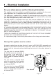
Thank you for buying your new CAPLE cooker. To ensure that you get the best results from your new CAPLE cooker, we strongly suggest that you read this instruction manual thoroughly before use. This manual contains installation advice, cleaning tips and a cooking guide, as well as other important facts about your CAPLE cooker. If treated with care, your CAPLE appliance should give you years of trouble-free cooking.
Important: This appliance is designed and manufactured solely for the cooking of domestic (household) food and is not suitable for any non domestic application and therefore should not be used in a commercial environment. This appliance guarantee will be void if the appliance is used within a non domestic environment i.e. a semi commercial, commercial or communal environment.
Important precautions and recommendations After having unpacked the appliance, check to ensure that it is not damaged and that the oven doors close correctly. In case of doubt, do not use it and consult your supplier or a professionally qualified technician. Packing elements (i.e. plastic bags, polystyrene foam, nails, packing straps, etc.) should not be left around within easy reach of children, as these may cause serious injuries.
• Fire risk! Do not store flammable material in the oven/s or in the storage compartment. • Make sure that electrical cables connecting other appliances in the proximity of the cooker cannot come into contact with the hob or become entrapped in the oven door/s. • Do not line the oven walls with aluminium foil. Do not place baking trays or the drip tray on the base of the oven chamber.
1 - Electrical Installation For your safety please read the following information: This appliance must be installed by a qualified technician according with the current local regulations and in compliance with the manufacturer instructions. This appliance is supplied with a moulded 13 amp three pin mains plug with a 3 amp fuse fitted. Should the fuse require replacement, it must be replaced with a fuse rated at 3 amp and approved by ASTA or BSI to BS 1362.
Electrical feeder cable connection The operations must be executed by a qualified technician. To connect the supply cable: - Remove the screws securing the cover “A” on the rear of the cooker (fig. 1.2). - Feed the supply cable through the cable clamp “D”. The supply cable must be of a suitable size for the current requirements of the appliance; see the section “Feeder cable section”. - Connect the wires to the terminal block “B” as shown in the diagram in figure 1.
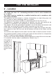
FOR THE INSTALLER 2 - Location This cooker has class “2/1” overheating protection so that it can be installed next to a cabinet. The cooker must be installed by a qualified technician and in compliance with local safety standards. The appliance may be installed in a kitchen, kitchen/diner or a bed sitting room, but not in a room or space containing a bath or a shower. The appliance must not be installed in a bed-sitting room of less than 20 m3.
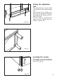
Fitting the adjustable feet The adjustable feet must be fitted to the base of the cooker before use. Rest the rear of the cooker an a piece of the polystyrene packaging exposing the base for the fitting of the feet. Fit the 4 legs by screwing them tight into the support base as shown in picture 2.3. Fig. 2.2 Fig. 2.3 Levelling the cooker The cooker may be levelled by screwing the lower ends of the feet IN or OUT (fig. 2.4). Fig. 2.
WARNING When raising cooker to upright position always ensure two people carry out this manoeuvre to prevent damage to the adjustable feet (fig. 2.5). WARNING Be carefull: do not lift the cooker by the door handle when raising to the upright position (fig. 2.6). WARNING When moving cooker to its final position DO NOT DRAG (fig. 2.7). Lift feet clear of floor (fig. 2.5). Fig. 2.5 Fig. 2.6 10 Fig. 2.
Stability bracket We recommend a stability bracket is fitted to the cooker. The type shown in fig. 2.8 can be purchased from most plumbers merchants and do it yourself (D.I.Y.) shops. Existing slot in rear of cooker Bracket Fig. 2.
Provision for ventilation – The appliance should be installed into a room or space with an air supply in accordance with BS 5440-2: 2000. – For rooms with a volume of less than 5 m3 - permanent ventilation of 100 cm2 free area will be required. – For rooms with a volume of between 5 m3 and 10 m3 a permanent ventilation of 50 cm2 free area will be required unless the room has a door which opens directly to the outside air in which case no permanent ventilation is required.
3 - Gas installation IMPORTANT NOTE This appliance is supplied for use on NATURAL GAS or LPG (check the gas regulation label attached on the appliance). – Appliances supplied for use on NATURAL GAS: they are adjusted for this gas only and cannot be used on any other gas (LPG) without modification. The appliances are manufactured for conversion to LPG. – Appliances supplied for use on LPG: they are adjusted for this gas only and cannot be used on any other gas (NATURAL GAS) without modification.
Gas connection The installation of the gas appliance to Natural Gas or LP Gas must be carried out by a suitably qualified and registered person. Installers shall take due account of the provisions of the relevant British Standards Code of Practice, the Gas Safety Regulations and the Building Standards (Scotland)(Consolidation) Regulations issued by the Scottish Development Department. Installation to Natural Gas Installation to Natural Gas must conform to the Code of Practice, etc.
Gas connection GB Cat: II 2H3+ The gas supply must use the nearest gas inlet pipe which is located at the left or the right hand side at the rear of the appliance (figs. 3.1, 3.3). The hose should also be connected in such away that it does not touch the floor. To screw the connecting tube operate with two spanners (fig.3.2). The unused end inlet pipe must be closed with the plug interposing the gasket.
Important prescriptions for gas connection 200 mm 200 mm 700 mm 700 mm Rear wall Rear wall Suggested area Suggested area for for gas mains connection connection gas mains Fig. 3.
Conversion to Natural Gas or to LPG Injectors replacement Select the injectors to be replaced according to the “Table for the choice of the injectors” (page 19). If the injectors are not supplied they can be obtained from the“Service Centre”. To replace the injectors: – Remove the gratings, the burner and the covers; – Using a wrench, substitute the nozzle injectors “J” (fig. 3.4 - 3.5) with those most suitable for the kind of gas for which it is to be used.
Adjusting of the minimum of the top burners In the minimum position the flame must have a length of about 4 mm and must remain lit even with a quick turn from the maximum position to that of minimum. The flame adjustment is done in the following way: – Turn on the burner – Turn the tap to the MINIMUM position – Take off the knob – With a thin screwdriver turn the screw F until adjustment is correct (fig. 3.6). Normally for LPG, the regulation screw is tightened up. F Fig. 3.
TABLE FOR THE CHOICE OF THE INJECTORS - Cat: II 2H3+ GB BURNERS Nominal Power [kW] Reduced Power [kW] 1,00 0,30 Auxiliary (A) G 30 - 28-30 mbar G 31 - 37 mbar G 20 20 mbar Ø injector [1/100 mm] Ring opening [mm] Ø injector [1/100 mm] Ring opening [mm] 50 - 72 (X) - Semi-rapid (SR) 1,75 0,45 65 - 97 (Z) - Rapid (R) 3,00 0,75 85 - 115 (Y) - Triple-ring (TR) 3,50 1,50 95 - 135 (T) - Left Oven 3,70 0,75 92 fully open* 140 5 * Left Grill 2,50 - 80 fully open* 12
LEFT OVEN Oven burner and grill burner replacement of injectors a) oven burner – Lift and remove the lower panel inside the oven. Fig. 3.7 – Remove the burner securing screw (fig. 3.7). – Withdraw the burner as shown in figure 3.8 and rest it inside the oven. Take care not to damage the wire to the ignition electrode and the safety valve probe. Fig. 3.8 – Using a 7 mm box spanner, unscrew the injector (indicated by the arrow in fig. 3.8) and replace it by the proper one according to the kind of gas.
Regulation of air supply to oven and grill burners Using a cross-head screwdriver, slacken the screw securing the air flow regulation collar (fig. 3.11 and 3.11) and move the collar forward or backward to increase or reduce the air aperture in accordance with gas type and the indications in the “TABLE FOR THE CHOICE OF THE INJECTORS”. Light the burner and check the flame. Fig. 3.12 Ring opening Fig. 3.
RIGHT OVEN Regulation of air supply to oven burner Oven burner replacement of injector Using a screwdriver, slacken the screw securing the air flow regulation collar (fig. 3.15) and rotate the collar clockwise or anti-clockwise to increase or reduce the air aperture in accordance with gas type and the indications in the “TABLE FOR THE CHOICE OF THE INJECTORS”. Light the burner and check the flame. – Lift and remove the lower panel inside the oven. – Remove the 2 screws securing the burner (fig. 3.13).
LEFT and RIGHT OVENS G Regulating of the oven minimum This needs to be done only for the oven burner (the grill of the left oven is a fixed capacity) by acting on the thermostat. Considering that in the minimum position the flame must have a length of about 4 mm and must remain lit even with a brusque passage from the maximum position to that of minimum. The flame adjustment is done in the following way: – Light the oven taking the knob to max. position (230 ).
4 - Features and Technical Data 2 2 4 1 3 Fig. 4.1 Cooking hob - (Fig. 4.1) 1. 2. 3. 4. Auxiliary burner (A) Semi-rapid burner (SR) Rapid burner (R) Triple-ring burner (TR) 1,00 1,75 3,00 3,50 kW kW kW kW Important Note: The electric ignition is incorporated in the knobs. The appliance has a safety valve system fitted, the flow of gas will be stopped if and when the flame should accidentally go out.
Control Panel Fig. 4.2 1 2 3 4 5 6 7 8 9 10 Control panel - Controls description - (Fig. 4.2) 1. Left gas oven/gas grill control knob 2. Left oven light control knob 3. Minute counter 4. Right oven light control knob 5. Front left burner control knob 6. Rear left burner control knob 7. Central burner control knob 8. Rear right burner control knob 9. Front right burner control knob 10.
How To Use the Hob Burners Hob burners Each hob burner is controlled by a separate gas tap operated by a control knob (fig. 4.3) which has 3 positions marked on the control panel, these are: – Symbol ● : tap closed (burner off) – Symbol : High (maximum) – Symbol : Low (minimum) Fig. 4.3 - The maximum setting permits rapid boiling of liquids, whereas the minimum setting allows slower warming of food or maintaining simmering conditions of liquids.
Choice of burner The burner must be chosen according to the diameter of the pans and energy required. Fig. 4.4 Burners Pan diameter Auxiliary Semi-rapid Rapid Triple-ring 12 16 24 26 ÷ ÷ ÷ ÷ 14 24 26 28 cm cm cm cm do not use pans with concave or convex bases Saucepans with handles which are excessively heavy, in relationship to the weight of the pan, are safer as they are less likely to tip. Pans which are positioned centrally on burners are more stable than those which are offset.
5 - Minure counter The minute counter is a timed acoustic warning device which can be set for a maximum of 60 minutes. The knob (Fig. 5.1) must be rotated clockwise as far as the 60 minute position and then set to the required time by rotating it anticlockwise. Remember to turn the oven/s off manually. 28 Fig. 5.
6 - Left main gas oven Attention: the oven door becomes very hot during operation. Keep children away. General features It is advisable, upon first use, to turn the oven on to the maximum temperature (position ) to eliminate possible traces of grease from the oven burner. The same operation should be followed for the grill burner. Oven thermostat The temperature knob is numbered from 130 to 230 (fig. 6.1) indicating the increasing oven temperature value (see table 6.2).
Ignition of the oven burner 1) Open the oven door to the full extent. WARNING: Risk of explosion! The oven door must be open during this operation. 2) Lightly press and turn the temperature knob anti-clockwise (fig. 6.3) to the max position ( fig. 6.1). 3) Press the knob firmly until the burner lights. Never continue this operation for more than 15 seconds. If the burner has still not ignited, wait for about 1 minute prior to repeating the ignition.
Oven cooking Oven light For efficient oven preheating, we recommend that grill tray and shelf are removed from the oven and replaced after about 15 minutes. The cooker is equipped with a light that illuminates the oven to enable visually controlling the food that is cooking. This light is controlled by a switch knob (Fig. 6.5). Before introducing the food, preheat the oven to the desired temperature.
Ignition of the grill burner IMPORTANT: the grill must always be used with the oven door ajar and with shield "A” mounted (fig. 6.8). Do not grill with the oven door closed. Attention: the oven door becomes very hot during operation. Keep children away. WARNING. The heat shield and the oven door reach a very high temperature whilst in use. Fig. 6.6 1) Open the oven door to the full extent. WARNING: Risk of explosion! The oven door must be open during this operation.
Use of the grill Very important: the grill must always be used with the oven door slightly open and with shield "A” mounted (Fig. 6.8). Mount shield “A” which serves to protect the control panel from the heat. Turn on the grill, as explained in the preceding paragraphs and let the oven preheat for about 5 minutes with the door ajar. Introduce the food to be cooked, positioning the rack as close to the grill as possible. The drip tray should be placed under the rack to catch the cooking juices and fats.
7 - Right small gas oven Attention: the oven door becomes very hot during operation. Keep children away. General features The oven is furnished completely clean; it is advisable, however, upon first use, to turn the oven on to the maximum temperature (position ) to eliminate possible traces of grease from the oven burner. Oven thermostat The temperature knob is numbered from 130 to 230 (fig. 7.1) indicating the increasing oven temperature value (see table 7.2).
Ignition of the oven burner 1) Open the oven door to the full extent. WARNING: Risk of explosion! The oven door must be open during this operation. 2) Lightly press and turn the temperature knob anti-clockwise (fig. 7.3) to the max position ( fig. 7.1). 3) Press the knob firmly until the burner lights. Never continue this operation for more than 15 seconds. If the burner has still not ignited, wait for about 1 minute prior to repeating the ignition.
Oven cooking Oven light For efficient oven preheating, we recommend that grill tray and shelf are removed from the oven and replaced after about 15 minutes. The cooker is equipped with a light that illuminates the oven to enable visually controlling the food that is cooking. This light is controlled by a switch knob (Fig. 7.5). Before introducing the food, preheat the oven to the desired temperature.
Recommended cooking temperature Food CAKES Victoria sandwich Small cakes/buns Maidera cake Fruit cake Rich fruit cake Scones °C °F Gas Mark Shelf Position* Cooking Time (approx) 190 190 180 170 150 225 375 375 350 325 300 425 5 5 4 3 2 8-9 2 or 3 1 and 2 2 or 3 3 3 or 4 2 20-25 mins 15-20 mins 20 mins 13/4 hours 21/2 hours 8-10 mins 425 400 400-410 400-410 8-9 6 6 6 2 2 1 or 2 1 or 2 10-20 20-30 30-35 40-45 225 220 230 425 425 450 7-8 7 8 2 1 or 2 2 35-55 mins 15-20 mins 20 mins 190 190
8 - Cleaning and Maintenance General advice – When the appliance is not being used, it is advisable to keep the gas tap closed. – Every now and then check to make sure that the flexible tube that connects the gas line or the gas cylinder to the appliance is in perfect condition and eventually substitute it if it shows signs of wearing or damage. – The periodical lubrication of the gas taps must be done only by specialized personnel. – If a tap becomes stiff, do not force; contact your local Service Centre.
Enamelled parts All the enamelled parts must be cleaned with a sponge and soapy water or other nonabrasive products. Dry preferably with a microfibre or soft cloth. Acidic substances like lemon juice, tomato sauce, vinegar etc. can damage the enamel if left too long. Stainless steel, aluminium parts and silk-screen printed surfaces Clean using an appropriate product. Always dry thoroughly. IMPORTANT: these parts must be cleaned very carefully to avoid scratching and abrasion.
Burners They can be removed and washed with soapy water only. They will remain always perfect if cleaned with products used for silverware. After cleaning or wash, check that burner-caps and burner-heads are dry before placing them in the respective housings. Note: To avoid damage to the electric ignition do not use it when the burners are not in place. Correct replacement of the burners It is very important to check that the burner flame distributor F and the cap C has been correctly positioned (see figs.
Triple ring burner The triple ring burner must be correctly positioned (see fig. 8.5); the burner rib must be enter in their logement as shown by the arrow see fig. 8.3). Then position the cap A and the ring B (fig. 8.4 - 8.5). The burner correctly positioned must not rotate (fig. 8.4). T S Fig. 8.3 A B Fig. 8.4 Fig. 8.
Fig. 8.6 Fig. 8.7 Oven doors Storage compartment The internal glass panel can be easily removed for cleaning by unscrewing the retaining screws (Fig. 8.6) The storage compartment is accessible through the pivoting panel (fig. 8.7). Do not use harsh abrasive cleaners or sharp metal scrapers to clean the oven door glass since they can scratch the surface, which may result in shattering of the glass. 42 Do not store flammable material in the ovens or in the storage compartment.
Inside of ovens The oven should always be cleaned after use when it has cooled down. The cavity should be cleaned using a mild detergent solution and warm water. Suitable proprietary chemical cleaners may be used after first consulting with the manufacturers recommendations and testing a small sample of the oven cavity. Abrasive cleaning agents or scouring pads/cloths should not be used on the cavity surface.
Removing the oven doors Fig. 8.10A The oven door can easily be removed as follows: – Open the door to the full extent (fig. 8.10A). – Attach the retaining rings to the hooks on the left and right hinges (fig. 8.10B). – Hold the door as shown in fig. 8.10. – Gently close the door and withdraw Fig. 8.10B the lower hinge pins from their location (fig. 8.10C). – Withdraw the upper hinge pins from their location (fig. 8.10D). – Rest the door on a soft surface.
Helpful Advice Trouble shooting Changing the Oven Cavity Light Bulb. Problem Food too brown but not cooked. If the oven light falls: 1. Before carrying out any work on the electrical parts of the appliance, the appliance must first be disconnected from the electrical supply. Remedy Turn down the oven temperature slightly and cook a little longer. Problem Food cooked but not brown enough. Remedy Increase temperature. 2.
CAPLE “Built-in” Service Should you require service at any time, please contact the Caple Helpline. Please check contact details at www.caple.co.uk. Caple have a nationwide service network of engineers who will respond quickly to your call. Always replace spare parts with genuine Caple spares. These are available from authorised Caple Service Centres or by mail order (please check contact details at www.caple.co.uk). When ordering parts always quote the model number and serial number of your appliance.