Traditional Range Cooker Gas Versions Instructions for Use, Installation and Servicing For use in GB, IE (Great Britain and Eire) This appliance has been certified for use in countries other than those stated. To install this appliance in these countries, it is essential to obtain the translated instructions and in some cases the appliance will require modification. Contact Redfyre for further information.
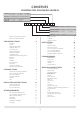
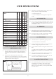
CONTENTS COVERING THE FOLLOWING MODELS COLOUR 00 = Cream 04 = Green 02 = Blue 10 = Pewter HOB LIDS 1 = Chrome Square FOUR OVEN HOB STYLE 0 = None 2 = LPG 03 = Black 12 = Claret 3 = Chrome Round 1 = Natural Gas 3 = Electric C R E ELECTRIC ELEMENT 0 = No HOT WATER BOILER 0 = None NUMBER OF OVENS GAS TYPE Appliance Commissioning Checklist Dealer and Installer Information USER INSTRUCTIONS Description General Lighting the Main Burner Turning the Burner off Care of the Cooker Vitreous Enamel Finis
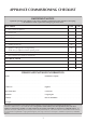
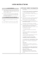
APPLIANCE COMMISSIONING CHECKLIST IMPORTaNT NOTICE Explain the operation of the appliance to the end user, hand the completed instructions to them for safe keeping, as the information will be required when making any guaranteed claims. FLUE CHECK Pass 1. Flue is correct for appliance 2. Flue flow test 3. Spillage test Fail GAS CHECK 1. Gas soundness & let by test 2. Standing pressure test mb 3.
USER INSTRUCTIONS Congratulations, you are now the proud owner of a new Redfyre Traditional Cooker. As manufacturers we are proud of the features and quality of construction of all our cookers. warranty and may affect your statutory rights. 1. Description 1.1 1.2 1.3 The Redfyre Traditional Range cooker is a heat-store cooker using a single burner powered by Natural or LPG Gas. The heat from this burner is built up and stored in the massive cast iron components of the cooker interior.
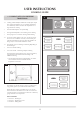
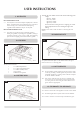
USER INSTRUCTIONS 3.2 If, after repeated attempts, the pilot does not light, contact your retailer or installer. 5.1 You can use hot soapy water and a cloth to clean the front and finish with a soft dry cloth to avoid streaking. To light the main burner: 5.2 We recommend you switch off the cooker at the mains and let it cool before cleaning or carrying out any maintenance work.
USER INSTRUCTIONS 9.3 V.E.D.C. cleaners Nylon Brush Cream cleaner Wire Brush Hot water & soap Redfyre parts appropriate cleaning methods 3 3 3 Surround 3 3 3 Hot plates 3 3 3 3 Oven Internal 3 3 3 3 Shelves 3 3 3 Oven Internal 3 Top Plate Vitreous enamel Seal 3 Oven Front 3 Sides 3 Doors 3 Chrome handles 3 Towel rail 3 Top plate 3 Hotplate lids 3 3 • Turn the gas burner off • Contact a competent service engineer to inspect the cooker 10. RUNNING IN 10.
USER INSTRUCTIONS AFTER SALES SERVICE INFORMATION 14. hot surfaces We provide a 2 year warranty and a nationwide network of Service Engineers 14.1 Protect children and the infirm from the hot surfaces of this cooker by providing a suitable guard. All parts of the cooker should be regarded as a working surface with the exception of the hob and door handles.
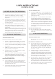
USER INSTRUCTIONS COOKING GUIDE 1. COOKING WITH YOUR REDFYRE TRADITIONAL 4 1.1 Cooking with the Redfyre Traditional is really quite simple. The cooker is designed to run at a constant temperature. You should only need to increase the temperature for a large amount of cooking: • The left-hand hotplate is for rapid boiling • The right-hand hotplate is for simmering or slow boiling • The top right oven is used for roasting and hot baking 1.
USER INSTRUCTIONS COOKING GUIDE TOP LEFT SIMMERING OVEN 2. SECRETS OF USING THE TRADITIONAL 2.1 Choose the right position in the cooker for your dish: high, moderate or low temperature, fast or slow cooking. Different areas of the Traditional are kept at different temperatures. 2.2 The temperature of each oven is different and within each oven it varies from top to bottom and side to side. Get to know your ovens and where to position shelves. Then cook your dish to perfection. 2.
USER INSTRUCTIONS This Hob has four radiant electric hobs with the following power ratings: 5. HOTPLATES left-back, 1800W left front, 1200W right-back, 1200W right-front, 1500W LEFT-HAND BOILING PLATE 5.1 The fairly fierce heat of this hotplate rapidly boils or browns dishes. Consider heating a frying/browning pan on the floor of the roasting oven to conserve heat before placing ingredients and oil/butter in the pan on this plate.
INSTALLATION INSTRUCTIONS TECHNICAL INFORMATION Model Gas Gas Type CAT. NOx class Pressure Inlet BP/High Injector B/PLow Input/Consumption High Low Output Water Country Four Oven I2H NG Nat. Gas 2 G20 20 mbar 9.3 mbar 2.9 1 x 2 .38 mm mbar 6.0 kW 3.0 kW 0.57m3/hr 0.29m3/hr n/a GB, IE Two Oven I2H NG Nat. Gas 2 G20 20 mbar 9.3 mbar 2.9 1 x 2.38 mm mbar 6.0 kW 3.0 kW 0.57 m3/hr 0.29 m3/hr n/a GB, IE Two Oven I LPG 3P Propane 2 G31 37 mbar 33.
INSTALLATION INSTRUCTIONS SITE REQUIREMENTS 1 NOTE: There is an optional plinth which increases all heights by 75mm. AR1562 2 NOTE: There is an optional plinth which increases all heights by 75mm.
INSTALLATION INSTRUCTIONS SITE REQUIREMENTS These instructions relate to all gas fired Two and Four Oven Traditional cookers with a conventional flue. These include models with and without a hot water boiler. CONSTRUCTION PARAMETERS 1.9 • Make sure it is inspected and tested for soundness, any defects rectified, or a new flue system provided where soundness is in doubt.
INSTALLATION INSTRUCTIONS SITE REQUIREMENTS Stainless Steel-Lined Prefabricated Chimneys 2.2 – Materials described in Building Regulations suited to solid fuel and oil burning appliances. These systems consist of two skins of stainless steel or a combination of stainless and galvanised steel incorporating high quality materials. Depending on the materials of combustion, these products can be used internally and externally. These products must be certified to BS4543.
INSTALLATION INSTRUCTIONS SITE REQUIREMENTS 4. termination 4.1 We would recommend the use of a suitably approved antidown draught cowl for gas operation.
INSTALLATION INSTRUCTIONS SITE REQUIREMENTS 4 AR1570 16
INSTALLATION INSTRUCTIONS SITE REQUIREMENTS 5. Wind effects On buildings 5.1 • For open flue appliances installed in rooms or internal spaces, where the open flue appliance has a rated input exceeding 7kW, that room or internal space shall be provided with a permanent opening having a minimum free area of 4.5 cm2 for every kW over 7kW. • The Traditional has a maximum rated input of 6kW so further ventilation should not be required. But if the room has another gas appliance (e.g.
INSTALLATION INSTRUCTIONS INSTALLATION 1. IMPORTANT 1.1 3. electrical connections This appliance should be installed according to regulations in force and only used in a well-ventilated space. Read these instructions before installing or operating. 1.2 The Redfyre Traditional must be installed by a competent person in accordance with the requirements of the Gas Safety Regulations (Installation and Use) and this person must be Corgi registered. 1.
INSTALLATION INSTRUCTIONS INSTALLATION 4.4 Should the mains lead of the appliance ever require replacing, we recommend that the operation is carried out 6 WIRING DIAGRAM FOR TRADITIONAL 2 OVEN COOKER AR1563 by a qualified electrician, who will replace it with a lead of the same size and temperature rating. Four-oven model: Boost Element and Electric Hob, or Boost Element and Electric Ovens 4.
INSTALLATION INSTRUCTIONS INSTALLATION 5. setting/adjusting door latch pins 5.1 Set the door latches once the Traditional is assembled: Setting: • Loosen locking flange nut and remove door latch pin, nut and black washer • Apply ‘Loctite’ to door pin and re-assemble door latch pin, washer and flange nut, but do not tighten flange nut • Fit door • Adjust door latch pin, until the door seal seats securely and evenly around the front plate.
INSTALLATION INSTRUCTIONS COMMISSIONING All tests are to be conducted under the rules in force following best practice procedures. In the UK these are the procedures laid down by CORGI and the Gas Safety and use Regulations. maximum in the room or adjacent rooms and keep interconnecting doors open. IF SPILLAGE PERSISTS, DISCONNECT THE COOKER AND SEEK EXPERT ADVICE. 1. ELECTRICAL TESTS 4. GAS RATE Electrical warning • Check the gas rate (natural gas models only).
SERVICING INSTRUCTIONS SERVICING/FAULT FINDING 1. SERVICING REQUIREMENTS This appliance must be serviced at least once a year by a competent person. All tests must be serviced by best practice as described by current CORGI recommendations. 1.1 Before any tests are undertaken on the appliance, conduct a gas soundness test for the property to ensure that there are no gas leaks prior to starting work. 1.
Replace the lead, retry. No Is the electrode wire detachable from the piezo in the valve? No Replace the pilot unit. Yes Correct and retry. Reset the electrode gap, retry. Is the valve being operated correctly? Yes Remove the electrode lead from the piezo. Operate the valve. Does a spark jump from the piezo to the valve body? Check for defective or damaged control knob spindle or cam operation. Check for correct location of piezo components. Correct and retry.
SERVICING INSTRUCTIONS REPLACING PARTS IMPORTANT It is essential that range cookers are serviced and flue ways inspected and cleaned at regular 12 month intervals. The work must be carried out by trained service engineers. The appliance should be turned off at least 12 hours before the arrival of the engineer to allow it to cool. • Remove the thermostat phial from the top oven and from inside the control compartment 1. GENERAL 1.1 All major components can be replaced from the front of the cooker. 1.
SERVICING INSTRUCTIONS REPLACING PARTS • Remove the two screws separating the burner from the aeration bracket. See diagram 5. 7 5 B C AR1553 3.1 AR1555 A • Undo the nut securing the pilot pipe and withdraw the pipe complete with injector hooked onto the olive. See diagram 7, Arrow C. To remove the injector: • Reverse the order of the above procedure to reassemble. Check for leaks and flame length. See diagram 8. • Undo the locknut holding the aeration bracket to the injector. See diagram 6.
SERVICING INSTRUCTIONS REPLACING PARTS • Reverse the order of the above procedure to reassemble. 8.1 • Check for gas leaks and the operation of the ignition system. • Replace the mag unit retaining nut and tighten. NOTE: This is a gas-tight seal 6. PIEZO 6.1 • Replace the thermocouple, interrupter block and leads and check for gas leaks. If a new piezo is required, it will be necessary to change the gas valve. Refer to Section 7. 8.2 7.
SERVICING INSTRUCTIONS REPLACING PARTS 12 15 AR1585 AR1588 • Raise the draught diverter cover to expose the TTB phial situated on the left side of the flue and remove the trim. See diagram 13. • Make sure the phial is vertical to allow the phial to pass through the access tube inside the cooker. • Remove the phial from the bracket by sliding the capillary tube through the slot and releasing the end out of the hole. Sea diagram 13. 9.
SERVICING INSTRUCTIONS REPLACING PARTS 12. boost element thermostat 11. HOBS • Pull the control knob off the spindle. Remove the four screws retaining the front panel. See diagram 18, Arrow B. 11.1 WARMING PLATE: • Remove the four fixing screws and lift the plate from its recess 18 NOTE: WHEN REPLACING THE GAS AND ELECTRIC HOBS, CLEAN THE EDGES OF BOTH THE COOKER TOP AND THE HOBS PRIOR TO APPLYING THE SEALANT.1 11.
SERVICING INSTRUCTIONS REPLACING PARTS • Reverse the order of the above procedure to reassemble. 13. changing between gas types In order to change between gas types you must change the following items: Component Nat Gas LPG Main Injector IN0032 IN0040 Pilot Injector 6028383 601815 Aeration Bracket 610295 610405 Gas Valve * GC0100 Data badge PR0423-TR A kit of parts is available for this. Always quote the Model number and serial number when ordering any spare parts.
SERVICING INSTRUCTIONS REPLACING PARTS 22. spare parts COMPONENT PART NUMBER BURNER UNIT GC0118 GAS VALVE GC100 PILOT BURNER SIT 140 B1 A2 0140020 602384 PILOT INJECTOR NG - SIT HOOK 27 LPG - SIT hook 23 LPG 602383 601815 THERMOCOUPLE TNAL 400 M9 602386 ELECTRODE SIT 0007226 602387 MAG UNIT GC0092 INTERRUPTER SIT 0.974.
SERVICE RECORDS 1st Service Date of Service:. . . . . . . . . . . . . . . . . . . . . . . . . . . . . . . . . Next Service due:. . . . . . . . . . . . . . . . . . . . . . . . . . . . . . . . Signed:. . . . . . . . . . . . . . . . . . . . . . . . . . . . . . . . . . . . . . . . Dealer’s Stamp 2nd Service Date of Service:. . . . . . . . . . . . . . . . . . . . . . . . . . . . . . . . . Next Service due: . . . . . . . . . . . . . . . . . . . . . . . . . . . . . . . Signed: . . . . . . . . . . . . . . .
For further advice or information please contact your local AGA Specialist With AGA’s policy of continuous product improvement, the Company reserves the right to change specifications and make modifications to the appliance described at any time. Manufactured by AGA Station Road Ketley Telford Shropshire TF1 5AQ England www.aga-web.co.uk www.agacookshop.co.uk www.agalinks.