Operating Manual Noise Activated Warning Sign GA902 www.castlegroup.co.
Thank you for buying a Castle product, I am sure you will find both the goods and the service to be of the highest quality but if not, then please feel free to write to me personally and I will ensure that your needs are dealt with immediately. This manual is designed to show you the operation of the goods you have purchased and a very brief insight into acoustics itself.
Copyright This manual is copyrighted with all rights reserved. Copying in part or in whole is prohibited without the prior written consent of Castle Group Ltd. Precautions • Only operate the instrument as described in this manual. • These are precision instruments, protect from shocks and vibrations.
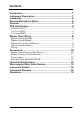
Contents Introduction............................................................................................... 1 Instrument Description ........................................................................ 1 Installation ................................................................................................. 2 Remote Microphone Option ................................................................ 2 Controls .................................................................................
Introduction The Castle GA902 instrument is designed to provide a visual warning of high noise levels requiring some form of action. In its standard form the sign is blank when OFF and clearly visible as an illuminated message when ON. Normally when illuminated the sign informs the viewer ‘Approved Hearing Protection Must Be Worn’. Other message may be supplied to special order.
Installation Choose a suitable location for the GA902 ideally mounted close to the main noise source on the wall, in a position where operators can easily see the display. The white box can be mounted at any convenient point using screws in the holes provided or alternatively may be hung on chains using the hooks provided.
Controls The GA902 is fitted with a TEST pushbutton which when pressed tests the PCB relay and the illumination of the lamps. Trip Setting The GA902 is set to trip at 80dB(A) which is is the required sound pressure level at the microphone to trip the unit. This level can easily be adjusted from 75dB(A) to 112dB(A) by the user.
PCB Identification The diagram below shows the position of the following components on the PCB. TRIP INCREASE RV2 1 Amp Fuse LK1 OPEN TRANSFORMER 1 2 3 SW1 4 CLOSE D RV1 + Calibration (RV1) This potentiometer gives +5dB adjustment to the calibration level and is factory set to match the microphone supplied. This control should not require any further adjustment. Trip Time (RV2) This potentiometer may be adjusted to control the tripped period (lamp on period) from 5 seconds to 30 seconds.
Reconnect the power to test the unit. WARNING: THERE ARE MAINS VOLTAGES PRESENT INSIDE THE UNIT WHEN SWITCHED ON Trip Level Switch SW1 dB 1 20dB 2 10dB 3 5dB 4 2.5dB 75 X X O O 77.5 X X O X 80 X X X O 82.5 X X X X 85 X O O O 87.5 X O O X 90 X O X O 92.5 X O X X 95 O X O O 97.5 O X O X 100 O X X O 102.5 O X X X 105 O O O O 107.5 O O O X 110 O O X O 112.
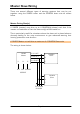
Master Slave Wiring There are several different types of warning systems that may be put together using the GA902 meter and the GA902A slave units as shown below. Master Driving Slave(s) A GA902 (master) may drive up to 4 GA902A(s) (slaves) such that if the master unit switches on then the slave unit(s) will also switch on. This is particularly useful for situations where the slave unit is placed above a doorway leading to the noisy environment to give advanced warning that hearing protection must be worn.
Master Driving Master A GA902 (master) may drive up to 10 GA902 master units such that if any master unit is on then all the masters will also switch on. This is useful where several units are located around a large factory where ear protection must be worn if any master unit switches on.
Master Driving Dumb Masters A GA902 master may be converted to a dumb master by removing the 0R wire link from position R32 and replacing it with a diode such as a IN4148 or IN4001 etc. In this mode the dumb master will only switch on from a local noise (self trip) but the master will switch on if either unit is switched on.
Typical Complex System An example is shown below where there is a mixture of masters, dumb masters and slaves all connected together to form a warning system: A B C D E on when self tripped or B or C on on when self tripped only on when self tripped only on when A, B, or C on on when B is on only A GA902 Master J7/1 L OUT L J7/2 N OUT E OUT N J7/3 J4/1 J4/2 POWER SUPPLY J7/1 B GA902 Dumb Master J7/2 J7/3 G N D S L A V E I/ O E L OUT L N OUT N E OUT E J4/1 J4/2 D GA902A Slave E GA902A Slav
Accessories Master/Slave Driving a Mini Beacon Both the GA902 and the GA902A are capable of driving a small amber beacon which attaches to the under-side of the warning sign. The beacon emits a high intensity pulse of light at a nominal flash rate of approximately 1 per second. Normally, the warning sign will be supplied with a mounting plate secured to its under-side. To install the beacon, pass the attached cable through the centre of the mounting plate and terminate at the lamp tray connector block.
Master Driving a Remote Beacon The GA902 is also capable of driving a single free-standing remote beacon. This could be particularly useful for situations in which a weatherproof visible sign is required indicating that hearing protection must be worn before entering a noisy environment. The remote beacon is of the rotating mirror type and emits a bright sweeping light. A bracket is provided in order to ensure correct vertical mounting.
Combinations A single GA902 Master is obviously limited by the amount of current it can supply to slaves and beacons. The table below outlines all of the current ratings for the various GA902 accessories. The total current drawn by the GA902, slaves and beacons must not exceed 1 Amp. GA902 Accessory selection guide Current (mA) Current (mA) UNIT VOLTAGE 110v 240v MASTER 172 79.
Technical Specification Trip Range: 75dB to 112.5dB in 2.
Warranty and After Sales Service Castle Group Ltd design and manufacture precision instruments, which if treated with reasonable care and attention should provide many years of trouble free service. In the event of a fault occurring, during the warranty period, the instrument should be returned to Castle Group Ltd, in its original packaging, or to an authorised agent. Please enclose a clear description of the fault or symptom.
Instrument Disposal The symbol shown here can be found on your instrument and means that the product is classed as electrical or electronic equipment and should be disposed of at the end of its life separately to your commercial or household waste. The Waste of Electrical and Electronic Equipment Directive (2002/96/EC) has been established to help reduce the influx on landfill sites and effectively treat hazardous substances by using best practices for the recovery and recycling of products.